
Device for measuring dimensions

Active Publication Date: 2012-01-05
TESA SE
View PDF40 Cites 21 Cited by
  • Summary
  • Abstract
  • Description
  • Claims
  • Application Information

AI Technical Summary

Benefits of technology

[0009]This solution has notably the advantage over the prior art to enable communication to be simplified and the measurement of a considerable number of probes to be effected simultaneously. The probes are autonomous at the instant of the measurement and do not perform other operations that could disrupt the measurement. This advantage over the prior art makes it possible to limit the consumption and perturbations and guarantees the punctuality, quality and accuracy of the measurement.

Problems solved by technology

Due to space requirements, the electronics are often external to the transducer.
One disadvantage of known probes is that each must be connected to an external measuring electronics that transforms the analog data coming from the inductive sensor and transforms and transmits them to a monitoring system.
In the case of wireless probes, the measurements are triggered by a measurement trigger signal and the measurements are then stamped with the time of the measurement, as the systems have variable delays.
Each measurement element can thus have a measurement delay which causes errors that are difficult to correct.
It is difficult to guarantee the synchronization of the transfers of the different elements when it is not known what they are doing neither at the instant of the measurement nor at the moment when the results are sent.
Furthermore, these systems rest on asynchronous transmission protocols between when the measurement is triggered and the measurement is recovered, which makes the transmission in these systems complicated, slow and renders the data not always comparable.
Finally, these systems can be caused to receive useless information at the time of measurement, which can cause delays in the processing.

Method used


Image

  • Device for measuring dimensions
  • Device for measuring dimensions
  • Device for measuring dimensions

Examples


Embodiment Construction

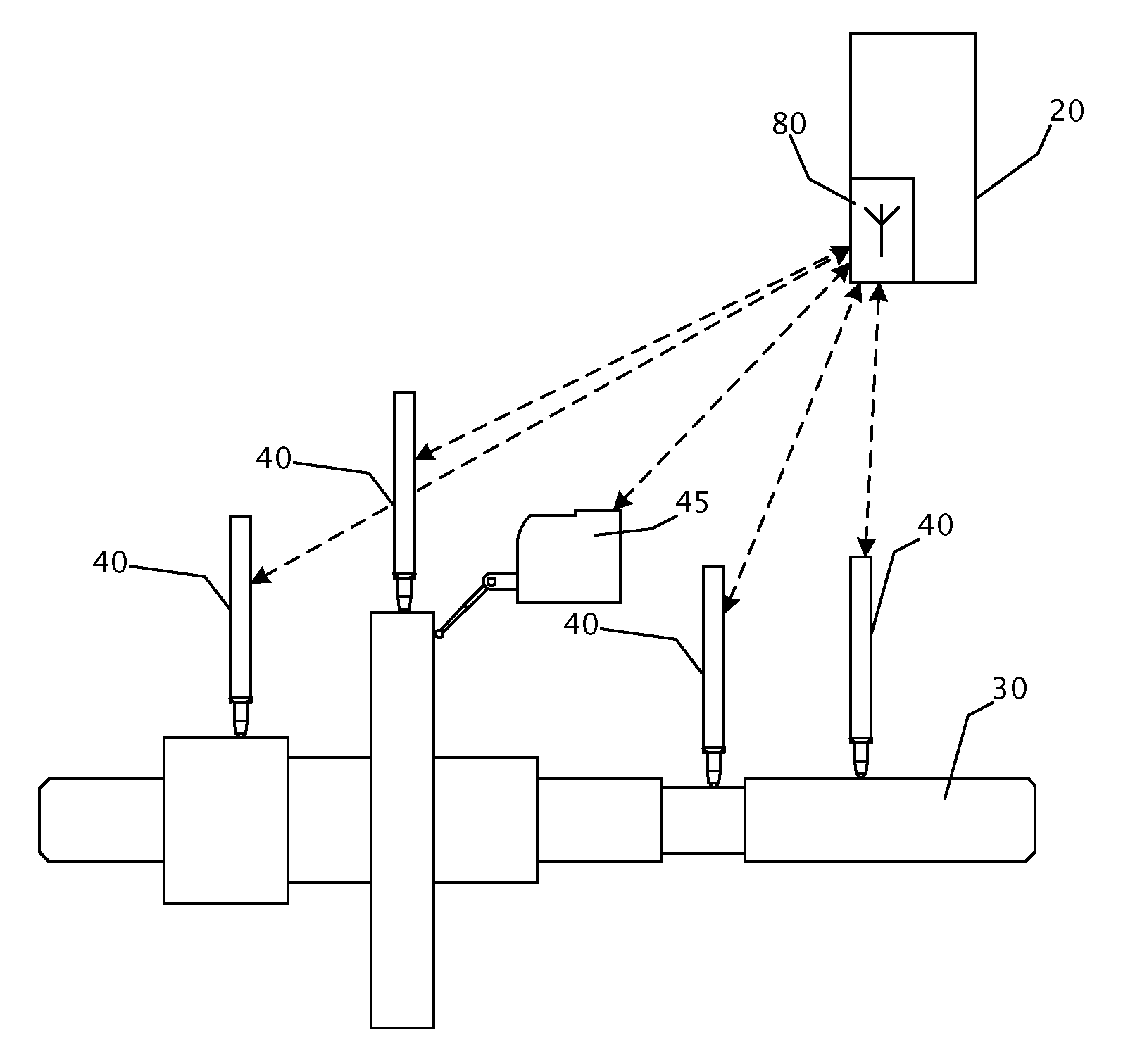
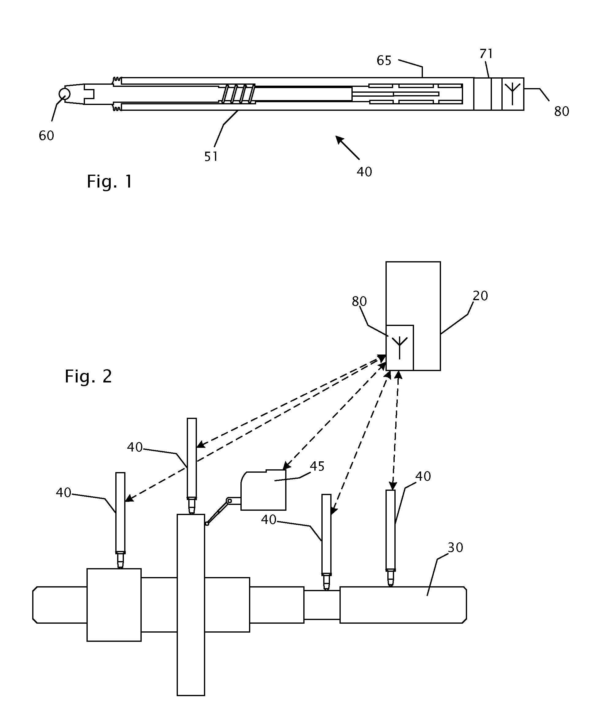
[0016]FIG. 1 illustrates an example of a length probe 40 that can be used in the frame of the invention. The probe 40 comprises a probe tip 60, for example a sphere of hard metal whose diameter is perfectly known, at the extremity of a rod 62 sliding inside a cylindrical casing 51. A bearing, not represented, or another suitable linear guiding device, enables the accurate axial sliding of the rod 62 and a perfectly reproducible, preferably rectilinear, movement of the probe tip 60.

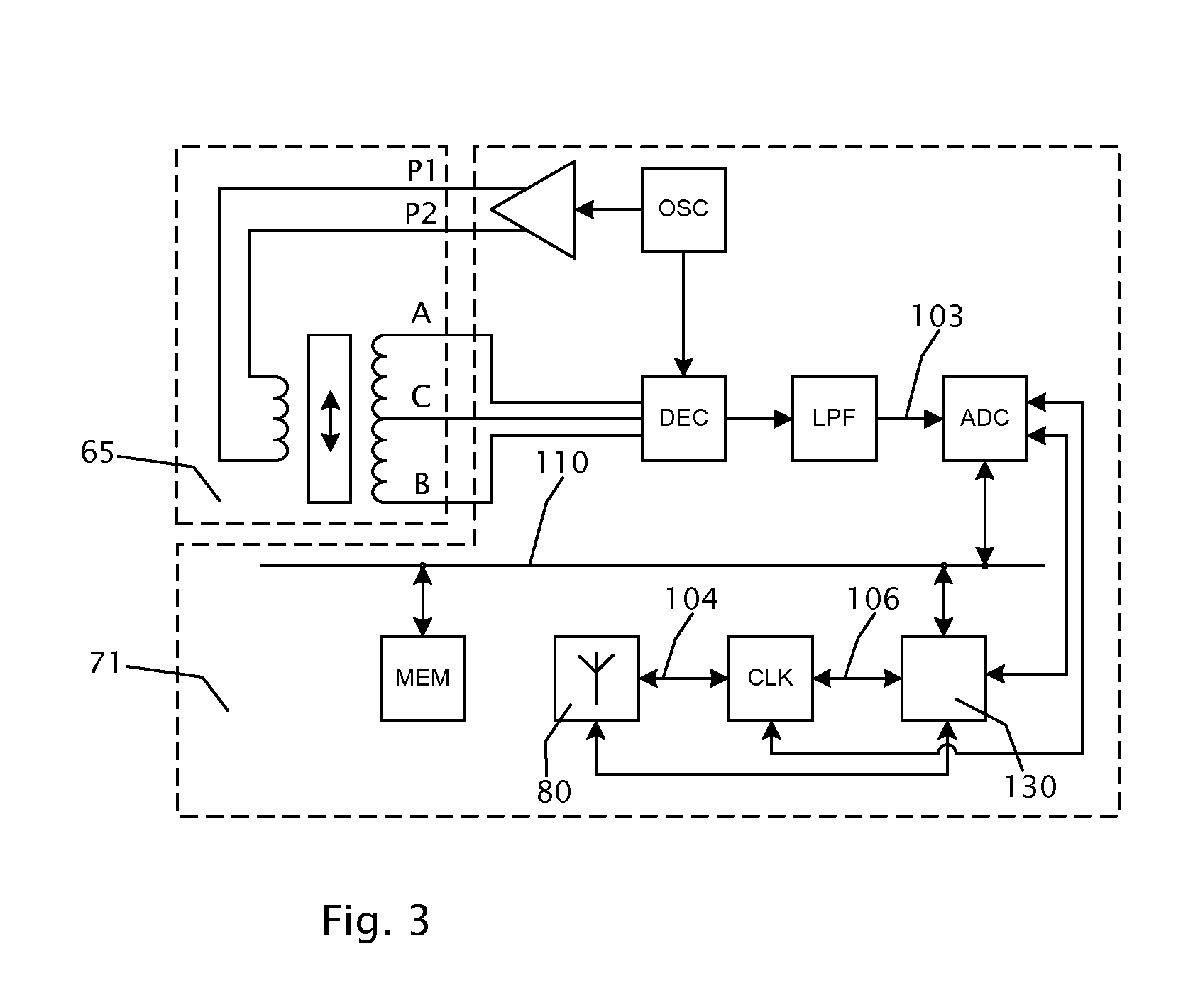
[0017]The probe 40 comprises a transducer 65 enabling the displacement of the rod 62 and of the probe tip 60 relative to the casing 51 to be measured instantaneously. The transducer 65 can be an inductive transducer, for example a linear differential transformer (LVDT—Linear Variable Differential Transformer) or an inductive half-bridge (HBT—Half Bridge Transformer) supplying an analog signal in AC whose amplitude depends in a known manner on the displacement of the probe tip 60. The invention can also inc...


PUM


Abstract

Measuring system having a plurality of probes for measuring lengths, each probe including a probe tip connected in removable fashion relative to a casing, a transducer supplying an electric signal that is representative of the position of said probe tip relative to the casing, a digital processing unit for sampling the signal from said transducer and transforming it into a digital representation of said position, and a bidirectional interface for a wireless communication network connecting said probes with a control unit. A method including a step during which the clocks of the digital processing units of the probes are synchronized through said bidirectional wireless interface and a step during which the control unit transmits commands determining the instant at which said electric signals are sampled.

Description

REFERENCE DATA[0001]The present application claims priority of European patent application EP10168374.6 filed on Jul. 2, 2010, the contents whereof are hereby incorporated by reference in their entirety.TECHNICAL FIELD[0002]The present invention relates to a system of sensors for measuring displacements. Embodiments of the present invention relate in particular to a multiple measuring system for measuring relative dimensions organized around a wireless communication network interfaced by a programming and monitoring system or by a data generation system that controls said measuring system by means of embedded clocks.BACKGROUND ART[0003]Measuring systems allowing several dimensions of a part to be measured simultaneously are known. These devices, also known by the designation multipoint measuring systems, are typically used in operations of quality control and dimensional verification of finished parts, in particular machined parts, but not only of parts obtained through automatic ma...

Claims


Application Information

Patent Timeline
IPC IPC(8): G06F15/00
CPCG01B2210/58G01B7/287G01B3/22G01B7/34G01B2210/60G06F15/00G06F15/0275G06F15/0283
Inventor JORDIL, PASCALHOCHET, BERTRANDMARILLER, SERGEPOMPILI, PIERRE
Owner TESA SE
Learn More