
Decoding device and method for rotary transformer based on single FPGA (Field Programmable Gate Array)

A resolver and processing device technology, applied to transformers, single motor speed/torque control, inductors, etc., can solve problems such as coarse errors, inflexible system structures, and inaccurate black and white dividing lines, and achieve simple communication, The effect of flexible system structure

Inactive Publication Date: 2012-04-04
LANZHOU JIAOTONG UNIV
View PDF3 Cites 19 Cited by
  • Summary
  • Abstract
  • Description
  • Claims
  • Application Information

AI Technical Summary

Problems solved by technology

The traditional angular position and speed detection is mainly based on the photoelectric encoder, but half of the black and white dividing line of each code track of the photoelectric encoder is always aligned with the black and white dividing line of the adjacent inner ring code track, so that the black and white The inaccurate delineation of the demarcation line causes shortcomings such as rough errors. With the development of the electronic industry and the improvement of the integration of electronic components, the signal processing circuit of the resolver becomes simple and reliable, and the price is also greatly reduced. Therefore, the resolver is used to realize The method of angular position and speed detection has been widely used in aerospace, industry, transportation and civil fields due to its advantages such as wide speed range, high precision, good dynamic response, simplicity and reliability.
At present, most resolver signal decoding is completed by a dedicated resolver analog-to-digital conversion circuit, and the microprocessor and CPLD are used to jointly complete the corresponding control, but the communication between the peripheral circuit and each module is more complicated, and System structure is not flexible

Method used


Image

  • Decoding device and method for rotary transformer based on single FPGA (Field Programmable Gate Array)
  • Decoding device and method for rotary transformer based on single FPGA (Field Programmable Gate Array)
  • Decoding device and method for rotary transformer based on single FPGA (Field Programmable Gate Array)

Examples


Embodiment Construction

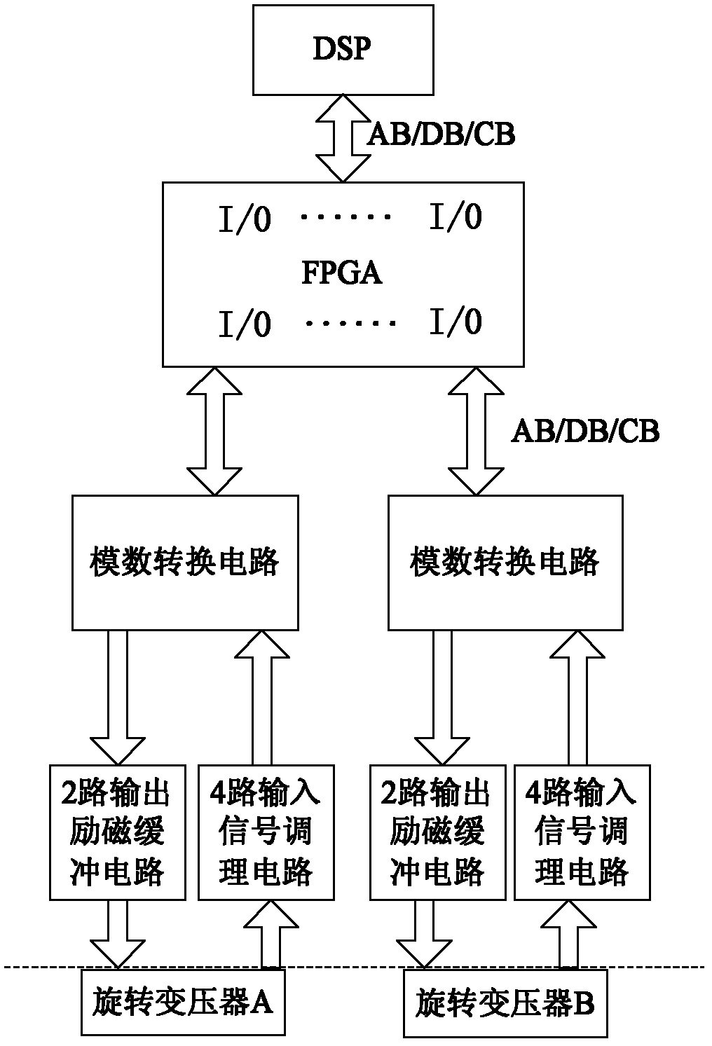
[0029] The preferred embodiments of the present invention will be described below in conjunction with the accompanying drawings. It should be understood that the preferred embodiments described here are only used to illustrate and explain the present invention, and are not intended to limit the present invention.

[0030] A resolver decoding processing device based on single FPGA, including DSP control circuit, FPGA circuit, analog-to-digital conversion circuit, input signal conditioning circuit, output excitation signal buffer circuit and resolver, FPGA circuit and analog-to-digital conversion circuit are connected by wires Together, the input end of the conditioning circuit of the input signal is connected to the analog-to-digital conversion circuit through a wire, the output end of the resolver is connected to the resolver through a wire, and the output end of the resolver is connected to the conditioning circuit of the input signal through a wire, and the input signal The o...


PUM


Abstract

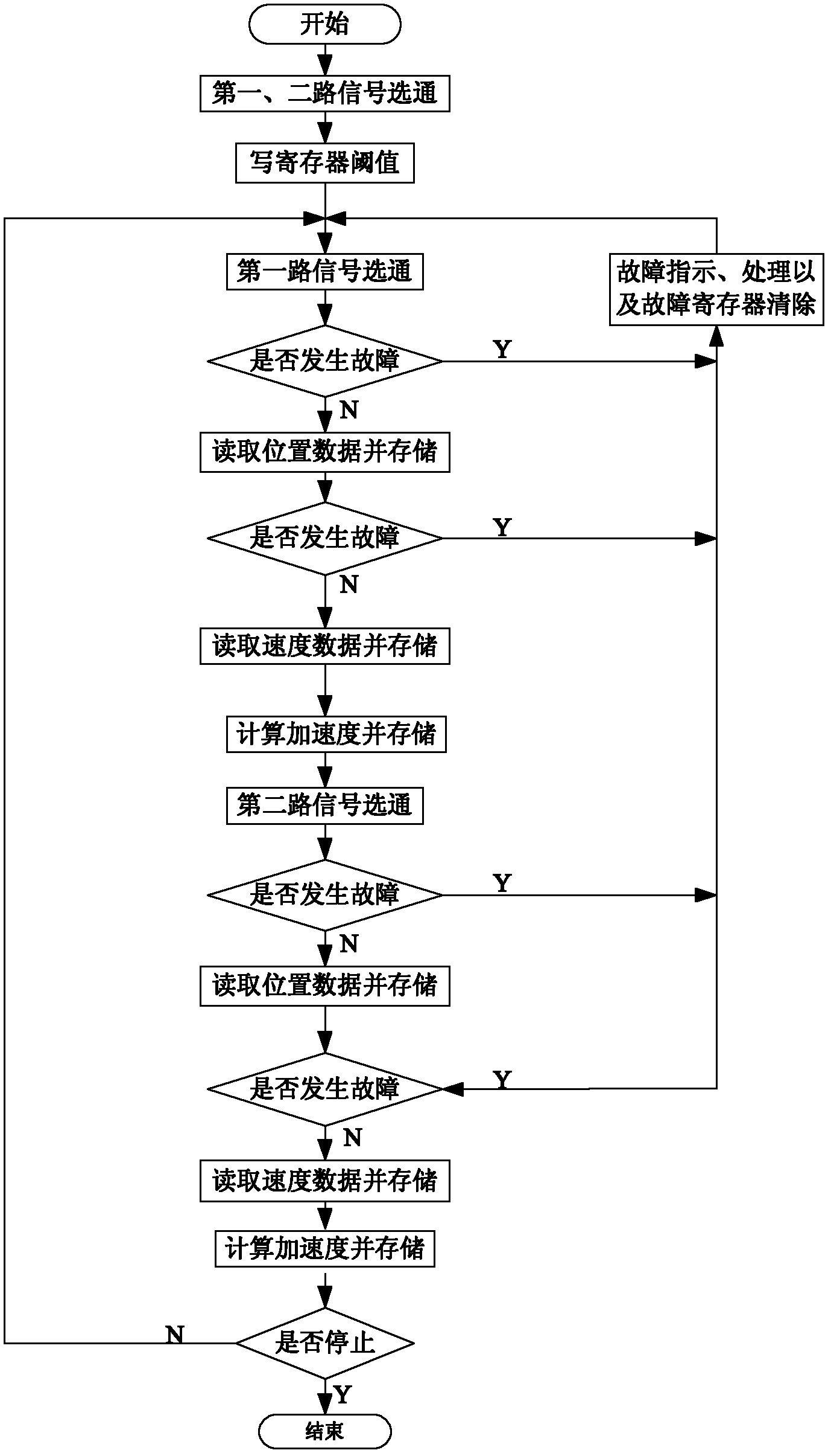
The invention discloses a decoding device for a rotary transformer based on a single FPGA (Field Programmable Gate Array), which comprises a DSP (Digital Signal Processing) control circuit, an FPGA circuit, an analogue-to-digital conversion circuit, an input signal conditioning circuit, an output excitation signal buffer circuit and a rotary transformer; the FPGA circuit is electrically connectedwith the analogue-to-digital conversion circuit; the input end of the output excitation signal buffer circuit is electrically connected to the analogue-to-digital conversion circuit, while the outputend of the output excitation signal buffer circuit is electrically connected to the rotary transformer; the output end of the rotary transformer is electrically connected to the input signal conditioning circuit; the output end of the input signal conditioning circuit is electrically connected to the analogue-to-digital conversion circuit; and the DSP control circuit is electrically connected with the FPGA circuit. Meanwhile, the invention also provides a decoding method; an analogue-to-digital conversion circuit is gated by the FPGA circuit; and the gated rotary transformer is subjected to acquisition and calculation of angle position, velocity and acceleration of a motor. The aim of simple communication among peripheral circuits and the modules and flexile system structure is realized.

Description

technical field [0001] The present invention relates to the field of rotary transformers, in particular to a single FPGA-based rotary transformer decoding processing device and method. Background technique [0002] In the force loading control system, it is necessary to perform closed-loop control on the angular position and speed of the motor to achieve high-fidelity force loading. Therefore, the accuracy of angular position and speed measurement is very critical to the system. The traditional angular position and speed detection is mainly based on the photoelectric encoder, but half of the black and white dividing line of each code track of the photoelectric encoder is always aligned with the black and white dividing line of the adjacent inner ring code track, so that the black and white The inaccurate delineation of the demarcation line causes shortcomings such as rough errors. With the development of the electronic industry and the improvement of the integration of elect...

Claims


Application Information

Patent Timeline
IPC IPC(8): H02P6/08H01F38/18G01R31/34
Inventor 蕫海鹰李晓青李帅兵李欣闫军
Owner LANZHOU JIAOTONG UNIV
Learn More