
Multilayer ceramic substrate

a ceramic substrate and multi-layer technology, applied in the direction of fixed capacitors, synthetic resin layered products, solid-state devices, etc., can solve the problem of not being able to achieve the desired substrate strength, and achieve the effect of increasing strength

Active Publication Date: 2012-01-05
MURATA MFG CO LTD
View PDF2 Cites 13 Cited by
  • Summary
  • Abstract
  • Description
  • Claims
  • Application Information

AI Technical Summary

Benefits of technology

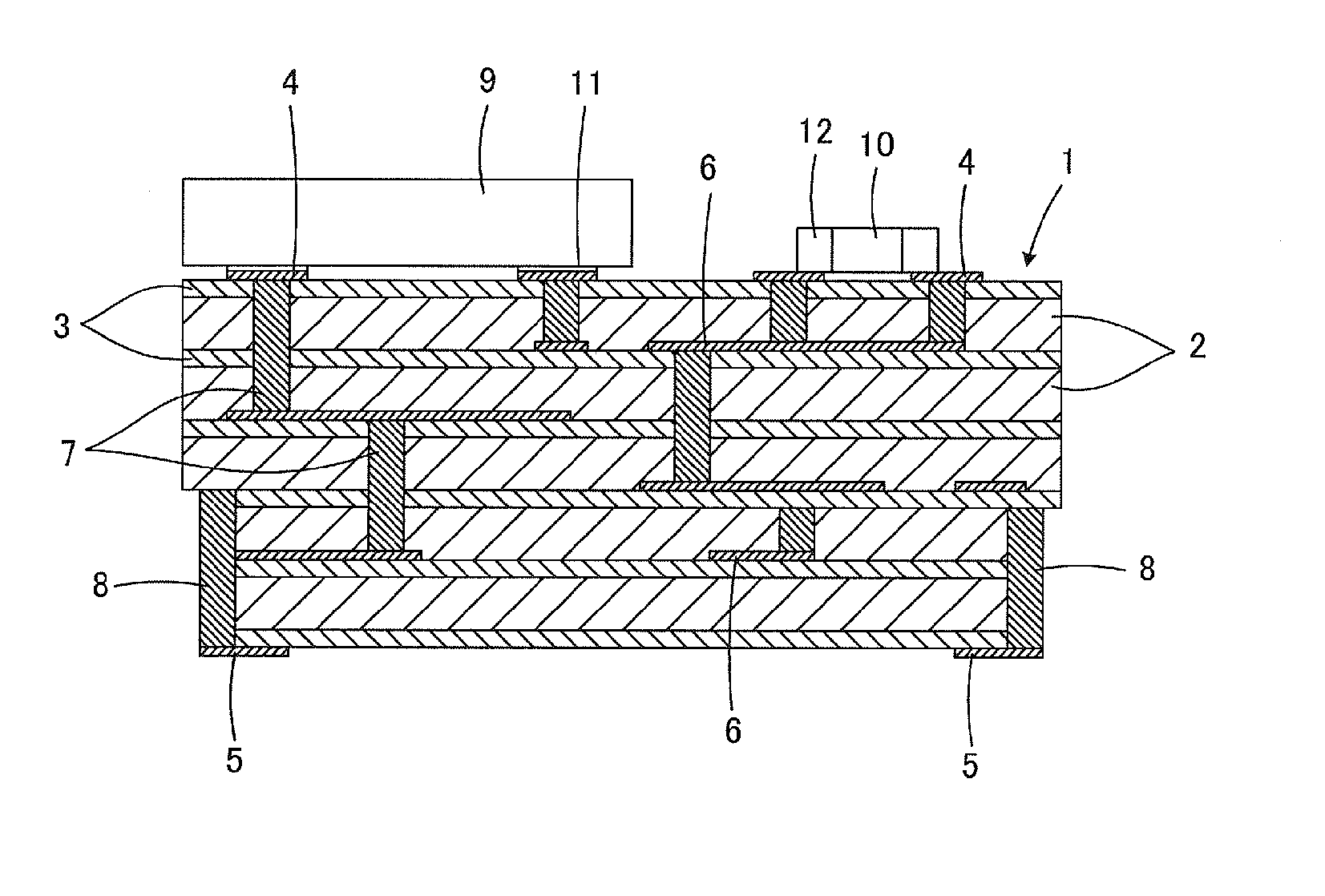
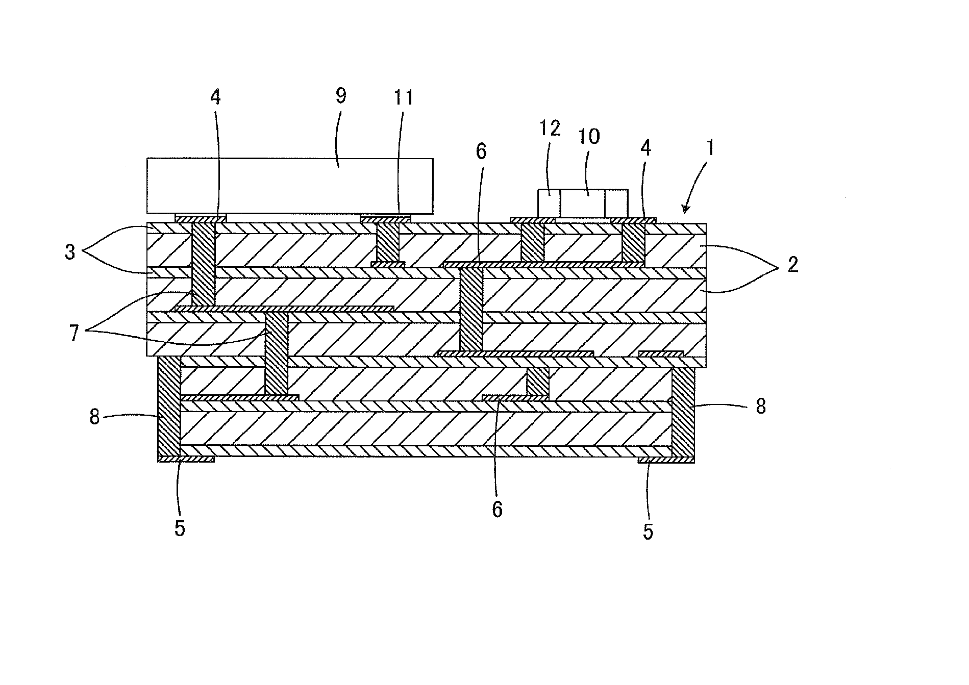
[0011]Preferred embodiments of the present invention provide a multilayer ceramic substrate which solves the problems described above and has a further increased strength.
[0014]Therefore, various preferred embodiments of the present invention are intended to, in brief, deposit fresnoite (Ba2TiSi2O8) which is a fine crystal phase other than celsian, in the base material layer by the addition of a Ti component to the base material layer, thereby improving the substrate strength.
[0016]The fresnoite has a crystal grain size equivalent to that of celsian, and has fine-grained crystals with a crystal grain size of about 0.5 μm, for example. Therefore, according to a preferred embodiment of the present invention, the fresnoite included in the first ceramic layer increases crystal grain boundaries in the first ceramic layer, and thus allows the development of cracking to be prevented, thereby allowing the strength of the multilayer ceramic substrate to be improved.
[0017]In a preferred embodiment of the present invention, when the second ceramic layer also includes fresnoite, the strength of the multilayer ceramic substrate can be further improved.
[0018]As described above, when the second ceramic layer also further includes fresnoite, the second ceramic layer defining the outermost layer is effective for the improvement of the strength, fracture toughness, and electrode peel strength of the multilayer ceramic substrate. More specifically, the strength properties of layers defining the outermost layers have a more dominant influence on the substrate strength, the fracture toughness, and the electrode peel strength, as compared with the strength properties of layers constituting the inner layers. In addition, the second ceramic layer is thinner as compared with the first ceramic layer, and the abundance ratio of fresnoite is thus higher in the second ceramic layer even when the fresnoite is deposited in the same way. With all these factors, when the second ceramic layer also includes fresnoite, the second ceramic layer defining the outermost layer is effective for the improvement of the strength, fracture toughness, and electrode peel strength as described above.

Problems solved by technology

However, because of the expensiveness of the glass powder, in the case of giving more consideration in terms of cost, for example, a non-glass based low-temperature sintering ceramic material is used which produces a glass component during the firing of a Ba—Al—Si based oxide ceramic or the like.
However, it has been found that it is not possible to achieve a desirable substrate strength, when the materials as disclosed in Japanese Patent Application Laid-Open No. 2009-170566, specifically, the Ba—Al—Si based oxide ceramic, is used as the base material layer whereas the alumina powder and the Ba—Al—Si based glass powder are used as the constrained layer in the multilayer ceramic substrate for which the constrained layer is formed to be thinner than the base material layer, as described in Japanese Patent No. 3601671, Japanese Patent Application Laid-Open No. 2002-94244, and Japanese Patent Application Laid-Open No. 2009-170566.

Method used


Image

  • Multilayer ceramic substrate
  • Multilayer ceramic substrate

Examples


experimental example

[0046]Next, an experimental example will be described which was carried out for confirming the advantageous effects of preferred embodiments of the present invention.

(1) Preparation of Green Sheets for Defining Base Material Layers

[0047]As starting raw materials, respective powders of SiO2, BaCO3, Al2O3, ZrO2, CaCO3, B2O3, MnCO3, TiO2, and Mg(OH)2 were prepared each with a grain size of 2.0 μm or less. Next, these starting raw material powders were weighed so as to provide the composition ratios shown in Table 1, and subjected to wet mixing and grinding, and then to drying, and the obtained mixture was subjected to calcination at 750° C. to 1000° C. for 1 to 3 hours to obtain raw material powders for base material layers. The BaCO3 was turned into BaO after the firing, the CaCO3 was turned into CaO after the firing, the MnCO3 was turned into MnO after the firing, and the Mg(OH)2 was turned into MgO after the firing. It is to be noted that the respective starting raw material powders...


PUM

PropertyMeasurementUnit
Pressureaaaaaaaaaa
Pressureaaaaaaaaaa
Pressureaaaaaaaaaa

Abstract

In order to enable non-shrinkage firing, the strength of a multilayer ceramic substrate is increased which is obtained by a method in which alternately stacking a base material layer and a constrained layer which is not sintered at the sintering temperature for the base material layer, and in a firing step, allowing the material of the base material layer to flow into the constrained layer while subjecting the base material layer to sintering, thereby achieving densification of the constrained layer. The base material layer and the constrained layer each include celsian, and the abundance of celsian is lower in the base material layer than in the constrained layer. In order to increase the strength of the base material layer, the addition of a Ti component, rather than an increased content of Al component which interferes with sintering of the base material layer, causes fresnoite to be deposited in the base material layers. The presence of fresnoite in the base material layers increases crystal grain boundaries in the base material layers, and thus prevents cracking, thereby allowing the strength of the multilayer ceramic substrate to be improved.

Description

BACKGROUND OF THE INVENTION[0001]1. Field of the Invention[0002]The present invention relates to a multilayer ceramic substrate, and more particularly, to a multilayer ceramic substrate that has improved strength and is produced in accordance with a non-shrinkage process.[0003]2. Description of the Related Art[0004]Japanese Patent No. 3601671 describes a method for manufacturing a composite laminate, in which a first sheet layer including a first powder and a second sheet layer including a second powder which is not sintered at a sintering temperature for the first powder are alternately stacked, and in a firing step, the first powder is sintered, whereas the material of the first sheet layer is allowed to flow into the second sheet layer to fix the second powder. This manufacturing method has been attracting attention as a technique for manufacturing a multilayer ceramic substrate, which can prevent shrinkage in the direction of the principal surface.[0005]When using the manufactur...

Claims


Application Information

Patent Timeline
IPC IPC(8): B32B7/02
CPCB32B18/00Y10T428/24942C04B2235/3206C04B2235/3208C04B2235/3215C04B2235/3217C04B2235/3232C04B2235/3244C04B2235/3262C04B2235/3409C04B2235/3418C04B2235/3436C04B2235/5436C04B2235/6025C04B2235/6582C04B2235/80C04B2235/96C04B2237/564C04B2237/582C04B2237/704H01G4/1227H01G4/30Y10T428/2495C04B35/195H01L2224/16225H01L2924/19105Y10T428/31504
Inventor MOTOYA, MACHIKOSUMI, TAKAHIRO
Owner MURATA MFG CO LTD
Learn More