Current source inverter device

a current source and inverter technology, applied in the direction of motor/generator/converter stopper, electronic commutator, dynamo-electric converter control, etc., can solve the problem of inability to arbitrarily adjust the power factor, and achieve the effect of saving calculation, reducing calculation load, and enhancing redundancy of control

Inactive Publication Date: 2011-12-29
MEIDENSHA ELECTRIC MFG CO LTD
View PDF4 Cites 1 Cited by
  • Summary
  • Abstract
  • Description
  • Claims
  • Application Information

AI Technical Summary

Benefits of technology

[0014]According to the configuration described above, it is possible to calculate the adjusting angle θα by setting the phase difference θy, and set the phase difference of the motor current with respect to the internal induced voltage to a suitable value by the calculated adjusting angle θα, and thereby achieve the set phase difference θy or the power factor cos θy between the internal induced voltage of the motor and the motor current. This serves to enhance redundancy of control, and thereby achieve a motor control optimized for load conditions.
[0018]According to the configuration described above, by addition of each condition, it is possible to hold unknown variables constant which unknown variables are contained in the conditional equation for determining the adjusting angle θα, and thereby save calculation, and thereby reduce the load of calculation.
[0020]According to the configuration described above, it is possible to reduce the load of calculation by the feature of selecting the adjusting angle θα by using the table.

Problems solved by technology

However, there has been a problem with this system that it is impossible to arbitrarily adjust the power factor.

Method used


Image

  • Current source inverter device
  • Current source inverter device
  • Current source inverter device

Examples


example 1

[0032]In this example, a vector diagram and others are used to obtain an equation expressing an adjusting angle for phase difference.

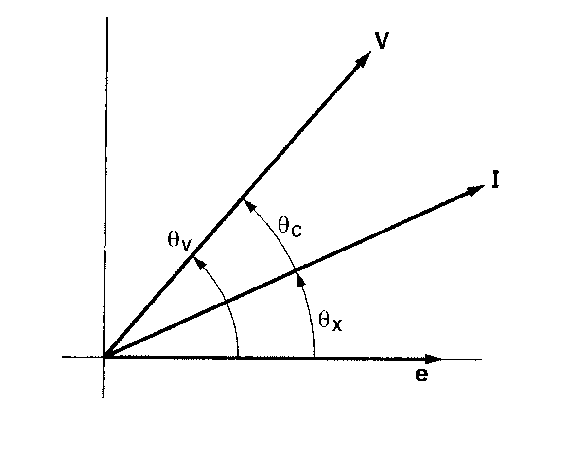
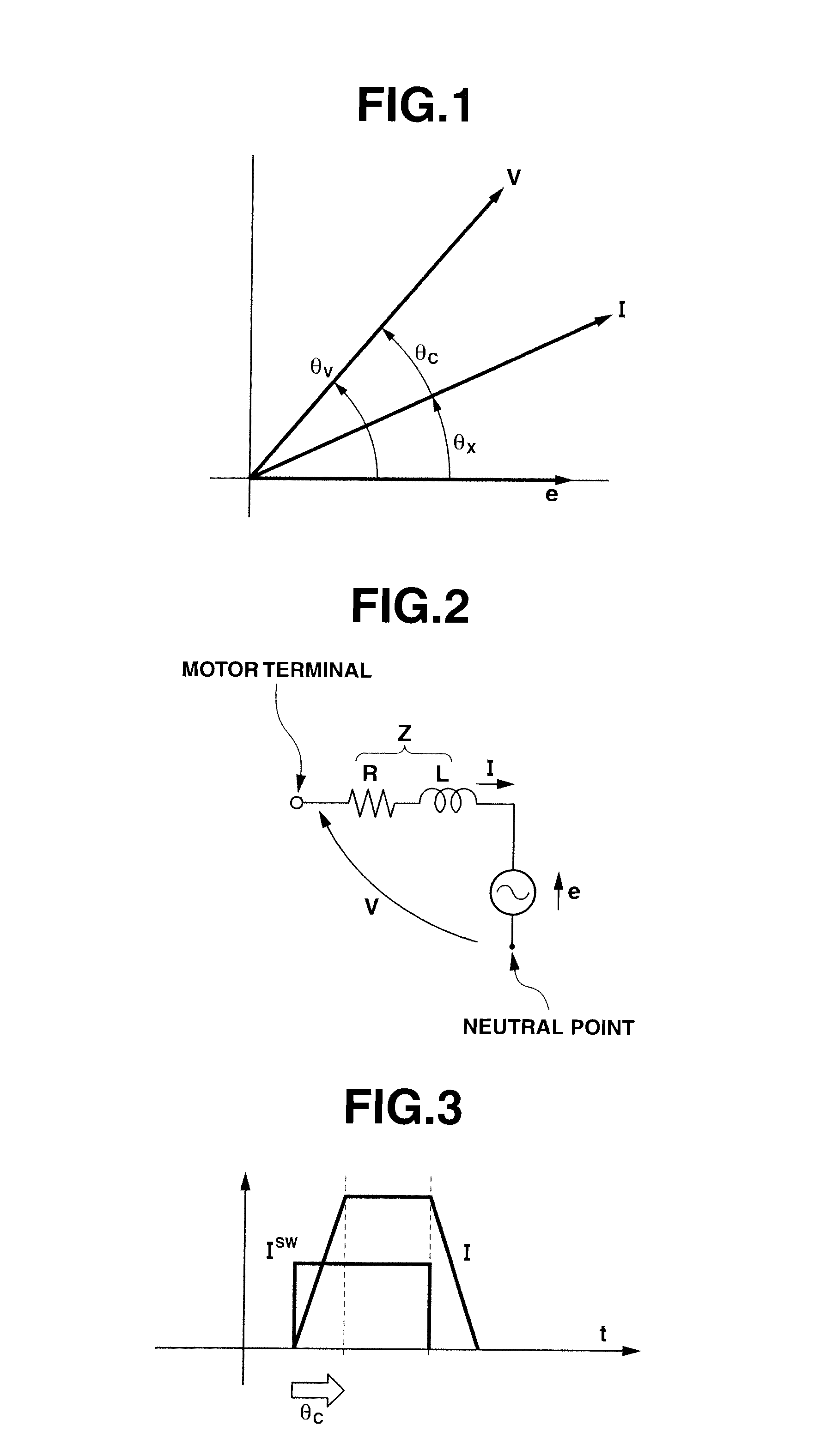
[0033]FIG. 1 is a vector diagram of internal induced voltage e of PM motor 4, terminal voltage V of PM motor 4 sensed by voltage sensor 3, and motor current “I” which flows through a coil of PM motor 4 and is sensed by a current sensor not shown. θv represents a phase difference between internal induced voltage e and terminal voltage V. θx represents a phase difference between internal induced voltage e and motor current I. θc represents a phase difference between terminal voltage V and motor current I. In this case, the power factor between internal induced voltage e and motor current I is represented by cos θx.

[0034]Further explanation is made with reference to FIG. 2. FIG. 2 is an equivalent circuit diagram of one phase section of PM motor 4. A motor coil impedance Z and internal induced voltage e are connected in series. Motor current I flows throu...

example 2

[0045]The calculation of equation (14) may cause a heavy calculation load because of inclusion of many trigonometric functions, and thereby cause a delay in the operation. Equation (14) can be simplified into equation (15) by ignoring R (R=0) in consideration that coil resistance R is small about several mΩ.

θα=tan-1LIcosθyk-LIsinθy-(ω·2L·IdcVdc+θy)(15)

[0046]This saving of calculation serves to reduce the calculation load.

example 3

[0047]Although the power factor can be arbitrarily set by equation (14), it is conceivable that the power factor is set to 1 in many cases. Accordingly, equation (14) can be simplified into equation (16) by setting the phase difference By to zero so that cos θy=1 and sin θy=0.

θα=tan-1ωLIkω+RI-(ω·2L·IdcVdc)(16)

[0048]This saving of calculation serves to reduce the calculation load.


PUM


Abstract

Disclosed is a current source inverter device which controls the power factor in an arbitrarily configurable manner without a magnetic pole position detector. The device is provided with a current source inverter; a motor supplied with alternating current power from the current source inverter; and a control means which detects the terminal voltage of the motor, calculates the motor's internal induced voltage and the motor current that flows in the motor based on the detected terminal voltage, and controls the current source inverter. The control means calculates the phase difference (θc) between the terminal voltage and the motor current, the phase difference (θx) between the motor current and the internal induced voltage, and the phase difference (θv) between the terminal voltage and the internal induced voltage. An adjustment angle (θα), which is the error in the phase difference between the motor current and the internal induced voltage when the set value of the phase difference (θx) is θy, is obtained from the conditional equation θα=θv−θy−θc.

Description

TECHNICAL FIELD[0001]The present invention relates to a current source inverter device provided with a control means for control with no magnetic pole position sensor, and relates to improvement in power factor.BACKGROUND ART[0002]PM motors are used in electric vehicles and others. In many cases, it is requested to implement an inverter control system by a sensor-less system for driving a PM motor. As a sensor-less system, an analogue filter system is known which estimates a magnetic pole position of a PM motor on a basis of an internal induced voltage of the PM motor (see non-patent document 1, for example).[0003]FIG. 6 shows an example of configuration of an inverter device (current source inverter device) based on sensor-less control depending on the internal induced voltage. This inverter device 10 includes a direct current power supply not shown, a 120-degree conduction inverter 2, a voltage sensor 3, a PM motor 4, an integrator circuit 5, and a logic conversion circuit 6. The ...

Claims


Application Information

Patent Timeline
Patent Type & Authority Applications(United States)
IPC IPC(8): H02P6/18H02P6/06H02P6/08H02P6/182H02P23/26H02P27/06
CPCH02P21/0003H02P23/0081H02P21/145H02P21/16H02P23/26
Inventor YAMAGUCHI, TAKASHITADANO, YUGOKAKEBAYASHI, TORU
Owner MEIDENSHA ELECTRIC MFG CO LTD
Why Eureka
Try Eureka