
Systems and methods for dielectric heating of ink in inkjet printers

Active Publication Date: 2011-12-22
SYNAPTICS INC
View PDF7 Cites 0 Cited by
  • Summary
  • Abstract
  • Description
  • Claims
  • Application Information

AI Technical Summary

Benefits of technology

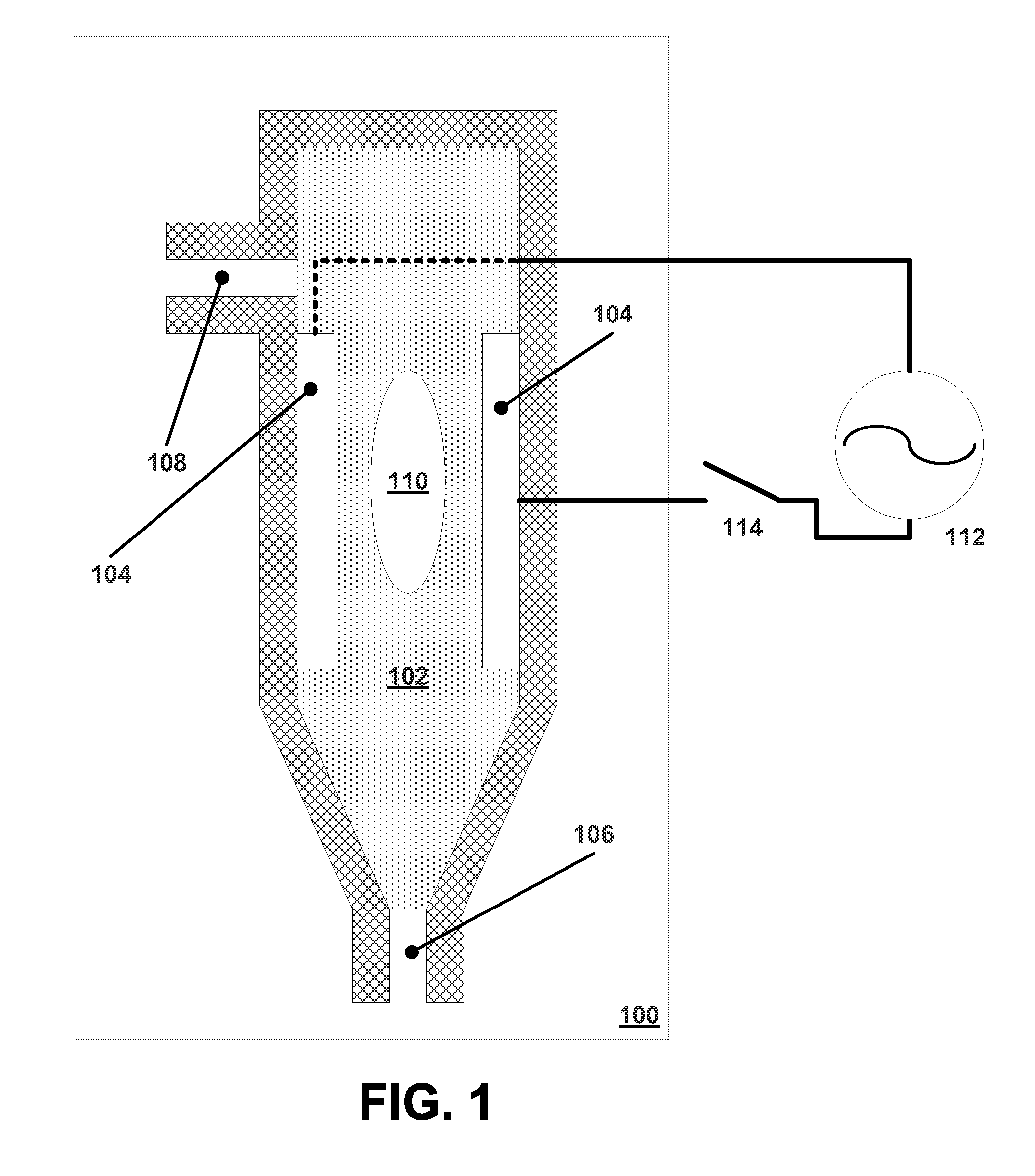
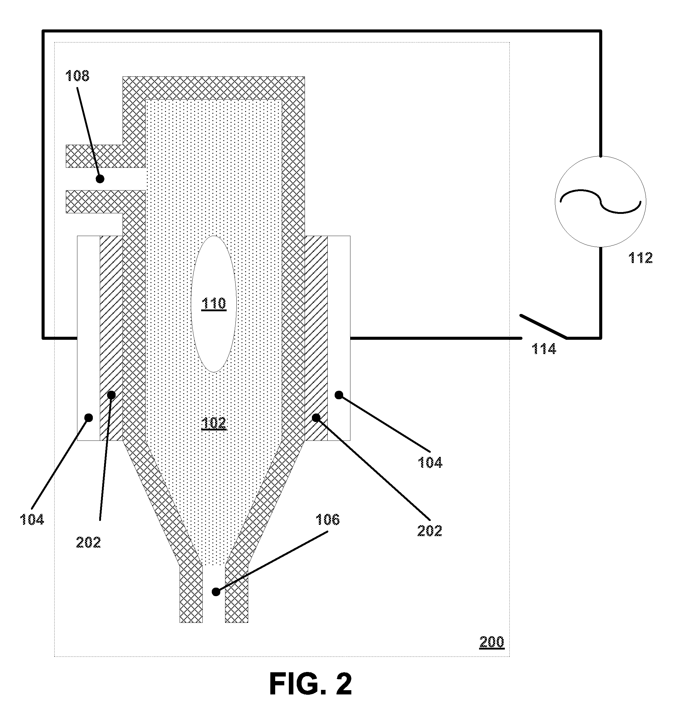
[0008]A novel inkjet delivery system, method and device are disclosed. A print head system comprises an ink reservoir, a nozzle and conductive plates. An alternating current signal at microwave frequencies produces an electric field between the conductive plates and across the ink reservoir. This causes explosive nucleation which causes a bubble in the ink to form which expels a drop of ink from the nozzle. In one embodiment, the conductive plates are thermally insulated from the ink reservoir. In another embodiment, electrolytes are added to the ink to improve the dielectric heating in the ink. In another embodiment, the walls of the ink reservoir can comprise texturing or projections to roughen the surface lowering the energy needed for nucleation.

Problems solved by technology

This causes explosive nucleation which causes a bubble in the ink to form which expels a drop of ink from the nozzle.

Method used


Image

  • Systems and methods for dielectric heating of ink in inkjet printers
  • Systems and methods for dielectric heating of ink in inkjet printers
  • Systems and methods for dielectric heating of ink in inkjet printers

Examples


Embodiment Construction

[0016]A detailed description of embodiments of the present invention is presented below. While the disclosure will be described in connection with these drawings, there is no intent to limit it to the embodiment or embodiments disclosed herein. On the contrary, the intent is to cover all alternatives, modifications and equivalents included within the spirit and scope of the disclosure.

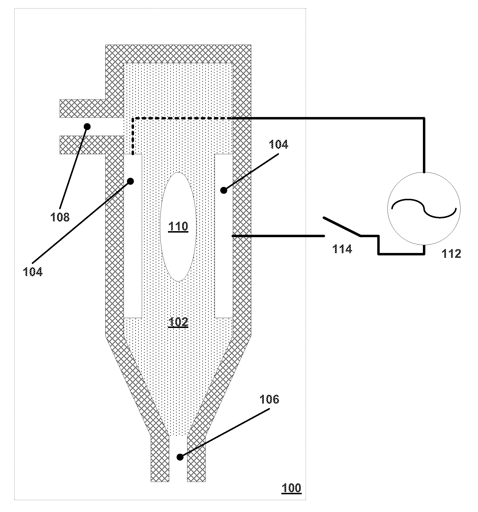
[0017]FIG. 1 illustrates a basic dielectric ink nozzle. Dielectric nozzle 100 comprises ink reservoir 102, conductive plates 104, nozzle 106, and ink cartridge intake 108. An alternating current is applied to conductive plates 104, and depending on the frequency of the current, the water in the ink will heat. Frequencies between 1 GHz and 20 GHz are known to cause water to heat. This can be supplied by a signal generator such as signal generator 112 and activated by switch 114. When sufficient heating occurs, the fast vaporization known as explosive nucleation takes place causing bubble 110 to form. Th...


PUM


Abstract

Dielectric heating is used to cause explosive nucleation of ink in an ink reservoir to expel a drop of ink from an inkjet print head. Conductive plates generate an alternating electric field at microwave frequencies across an ink reservoir causing the ink to heat. Since the ink is heated without heating the conductive plates, less heat dissipation of the inkjet print head is necessary.

Description

BACKGROUND OF THE INVENTION[0001]1. Field of the Invention[0002]The present invention relates generally to inkjet printing and specifically to the use of dielectric heating within an inkjet nozzle to expel a drop of ink.[0003]2. Related Art[0004]Inkjet printers work by squirting ink onto paper. They are non-impact printers in the sense that there is no physical contact between the paper and the print head to render images on a sheet of paper (or other medium). Unlike other non-impact printers, such as laser printers, inkjet printers use aqueous ink to create the images on the paper.[0005]A typical inkjet print head comprises a plurality of nozzles which can simultaneously impart ink from the nozzle to the paper. Presently, the two major types of nozzles in widespread use are thermal nozzles and piezoelectric nozzles.[0006]The performance of the thermal nozzle is constrained by the ability of the nozzle to dissipate heat from a heating element contained in the nozzle to heat the ink....

Claims


Application Information

Patent Timeline
IPC IPC(8): B41J29/38B41J2/175B41J2/06
CPCB41J2/14096
Inventor CHANDLER, MICHAEL O.
Owner SYNAPTICS INC
Learn More