Multi-disc air diffuser

Inactive Publication Date: 2011-12-15
ANT21
View PDF2 Cites 12 Cited by
  • Summary
  • Abstract
  • Description
  • Claims
  • Application Information

AI Technical Summary

Benefits of technology

[0024]An object of the present invention is to provide, for solving the problems, a multi-disc air diffuser in which a part of an air nozzle formed the upper surface of a disc is exposed to outside so that uniform and minute air bubbles are generated and diffused over a large area, thereby increasing an contact surface between gas and liquid in an aeration tank and the efficiency of mass transfer between gas and liquid.
[0025]Another object of the present invention is to provide a multi-disc air diffuser in which, when the air pressure is raised by introducing and depositing sludge, a disc is deformed elastically to prevent effectively an air nozzle from clogging.
[0026]Still another object of the present invention is to provide a multi-disc air diffuser in which the possibility of troubles can be reduced by minimizing a pressure load.
[0029]As described above, according to the present invention, by exposing a part of the air nozzle formed the upper surface of each of the discs, uniform and minute air bubbles are supplied over a large area in a great quantity. Thus, it is possible to increase the contact area between gas and liquid in the aeration tank and the efficiency of mass transfer between gas and liquid.
[0030]Further, in case that the air pressure is raised by introducing and depositing sludge, the discs can be deformed elastically. Thus, it is possible to prevent effectively the air nozzle from clogging.
[0031]Further, because it becomes possible to generate uniform air bubbles without increasing their size, the number and the time of running the air blower can be reduced, thereby decreasing considerably the cost of electric energy.

Problems solved by technology

Today, as the industrialization and the urbanization continues to increase, the environmental pollution is getting worse and the various types of wastewater, dirty water and sewage are discharged.
Thus, facilities for treating them have also highly developed and costs for treating have increased.
However, the method has disadvantages of having a long reaction time and a smell.
The aerobic treatment method has a disadvantage of needing energy for supplying oxygen.
However, because its reaction time is short and organic materials can be removed completely, the aerobic treatment method makes up the majority of wastewater treatment processes.
As described above, as the industrialization and the urbanization continues to increase, various types of wastewater, dirty water and sewage are discharged, and facilities for treating them have also highly developed and costs for treating have increased.
Now in wastewater treatment processes, in order to keep the dissolved oxygen DO in the aeration tank at an adequate concentration, an electric energy cost is highly required.
That is, by depositing sludge in the outside of the air diffuser, the generation of the air bubbles may be disturbed.
The disc type of air diffuser has some problems that air holes may be clogged by depositing of sludge and the capacity of an air blower should be large enough to keep the dissolved oxygen at a constant concentration, which is caused by a pressure load.
In this case, there is a problem that the air bubbles held in an air room cannot be generated uniformly and minutely by the lower surface of the upper disc.
As a result, there is a problem that the size of the air bubbles may be non-uniform or enlarged by growing the air bubbles in the lower surface of the upper disc.
Further, there is a problem that the air bubbles are not supplied steadily by a pressure load due to introduce and deposit sludge in the air nozzle.
Accordingly, the maintenance of the air diffuser becomes difficult.

Method used


Image

  • Multi-disc air diffuser
  • Multi-disc air diffuser
  • Multi-disc air diffuser

Examples


Embodiment Construction

[0040]A multi-disc diffuser according to embodiments of the present invention will be herein described with reference to the drawings. The following embodiments are provided for the purpose of illustrating the present invention, but not for the purpose of restricting the scope of the present invention. As will become apparent, changes and modifications may be made in the function and arrangement of the elements described in these embodiments without departing from the spirit and scope of the invention.

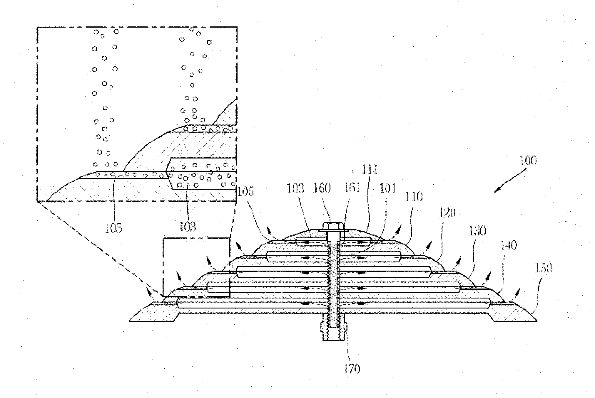
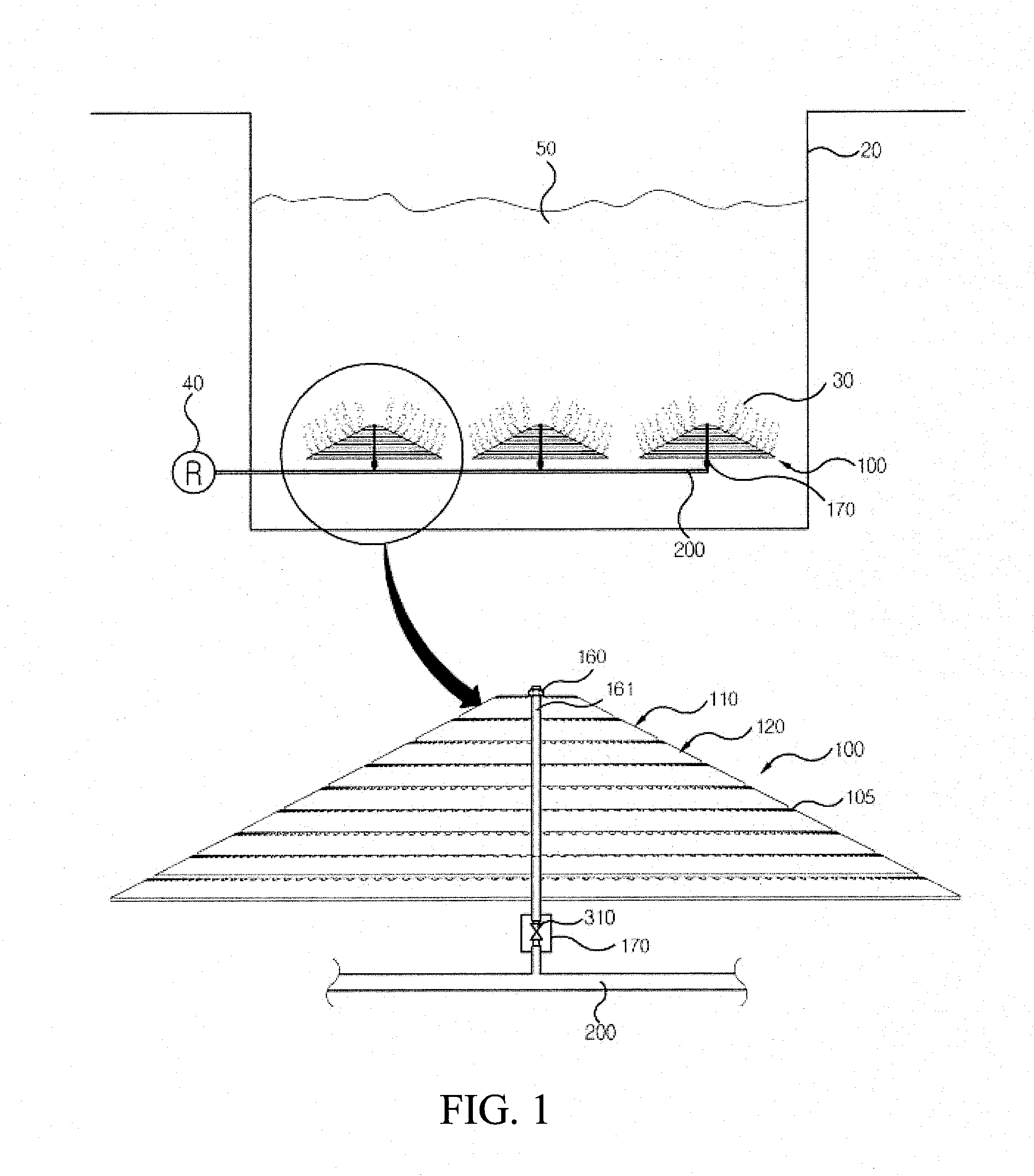
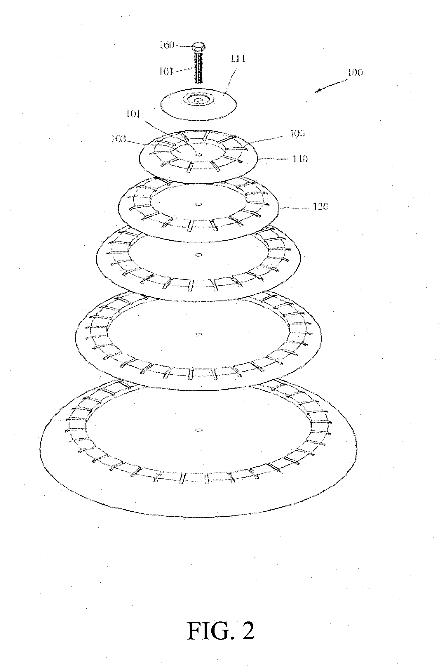
[0041]As shown FIGS. 1 to 8, a multi-disc diffuser 100 according to an embodiment of the present invention comprises a plurality of discs 110˜150 which becomes smaller as it goes to upper layer, a bolt 160 for joining the discs 110˜150; and a backflow prevention unit 170. A cover 111 is coupled on a top disc 110.

[0042]In more detail, each of the discs 110˜150 has an upper surface, a lower surface more than the upper surface, and the outer side surface inclined.

[0043]A bolt joint sectio...


PUM

PropertyMeasurementUnit
Widthaaaaaaaaaa
Flexibilityaaaaaaaaaa
Circumferenceaaaaaaaaaa

Abstract

A multi-disc air diffuser according to the present invention comprises a bolt having a vent groove formed in a longitudinal direction thereof; a plurality of discs, each of the discs having a bolt joint section to be passed through the bolt, an air room for holding the air supplied through the vent groove, and a nozzle section having a plurality of nozzles which are arranged in an end part of the air room at a regular size and intervals, wherein the lower surface of each of the discs is more than the upper surface thereof and the outer circumference surface of each of the discs is formed to be inclined; and a backflow prevention section for joining to an end part of the bolt to adhere closely the discs to one another, connecting the vent groove to an air supply pipe, and having a check valve to prevent the air flowing backward from the vent groove to the air supply pipe.

Description

BACKGROUND OF THE INVENTION[0001](1) Field of the Invention[0002]The present invention relates to an air diffuser which provides air or gas to a wastewater treatment plant, a combined septic tank, an aerobic reactor such as an aerobic fermentation tank, or a fish-breeding tank, which require adequate dissolved oxygen. More particularly, the present invention relates to a multi-disc air diffuser which can supply uniform and minute air bubbles in a great quantity over a large area of an aeration tank so that the concentration of dissolved oxygen is increased, thereby making it possible to treat wastewater efficiently.[0003](2) Description of the Related Arts[0004]Today, as the industrialization and the urbanization continues to increase, the environmental pollution is getting worse and the various types of wastewater, dirty water and sewage are discharged. Thus, facilities for treating them have also highly developed and costs for treating have increased.[0005]Now in order to treat th...

Claims


Application Information

Patent Timeline
IPC IPC(8): B01F3/04
CPCB01F3/04262B01F2003/04276C02F3/201B01F2003/04375B01F2003/04333Y02W10/10B01F23/23125B01F23/231267B01F23/23123B01F23/23127
Inventor KO, MYUNG-HANKWON, BYONG-CHEOLPARK, SUNG-HAKO, KYUNG-HANKIM, SANG-WOOLEE, SEUNG-JINYANG, JAE-KYUNGBAEK, KYOUNG-RYEOLYOON, DAE-HWANPARK, KIL-HOO
Owner ANT21
Why Eureka
Try Eureka