
Optical measurement cell

Inactive Publication Date: 2011-12-08
HORIBA LTD
View PDF1 Cites 14 Cited by
  • Summary
  • Abstract
  • Description
  • Claims
  • Application Information

AI Technical Summary

Benefits of technology

[0015]According to the present invention constructed as mentioned above, it becomes possible to alter the cell length while reducing the manufacturing cost and the spacer can be securely positioned at a desired position.

Problems solved by technology

However, since a processing cost for the process of bonding by welding or molecular bonding is high, there is a problem that the manufacturing cost thereof becomes high.
In particular, in the case where a material (such as, e.g., sapphire) having a corrosion resistance against a chemical solution such as hydrofluoric acid (HF) is used, since a processing cost of the sapphire is expensive in addition that the material per se is expensive, the manufacturing cost further becomes higher.
Therefore, if it is desired to measure a concentration of a solution using a different cell length, it is needed to prepare a different flow cell and there arises a problem that the cost is raised in addition.
However, the spacer sandwiched by the pair of light transmitting members may be displaced by a vibration or shock at a time of carrying or installing the flow cell, or due to a pressure, etc., of a sample solution at a time of measurement, and this may result in the flow channel changing in shape, or the spacer may enter an improper position such as a location on an optical path of the measurement light, and there may occur a problem of measurement error.
In addition, in the assembling process of the flow cell, when the spacer is interposed between the light transmitting members, it is difficult to determine where the spacer is positioned with respect to the light transmitting members, and further when the spacer is disposed and sandwiched between the pair of light transmitting members to be fixed, the spacer may be suffer from the problem of being undesirably misaligned.
Therefore, it is difficult to assemble the spacer and it is difficult to form the flow channel in a desired shape.

Method used


Image

  • Optical measurement cell
  • Optical measurement cell
  • Optical measurement cell

Examples


Embodiment Construction

[0026]The following describes an optical measurement flow cell 100 pertaining to an embodiment of the present invention referring to the accompanying drawings.

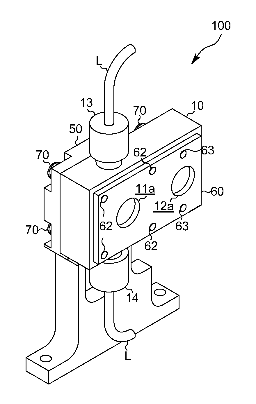
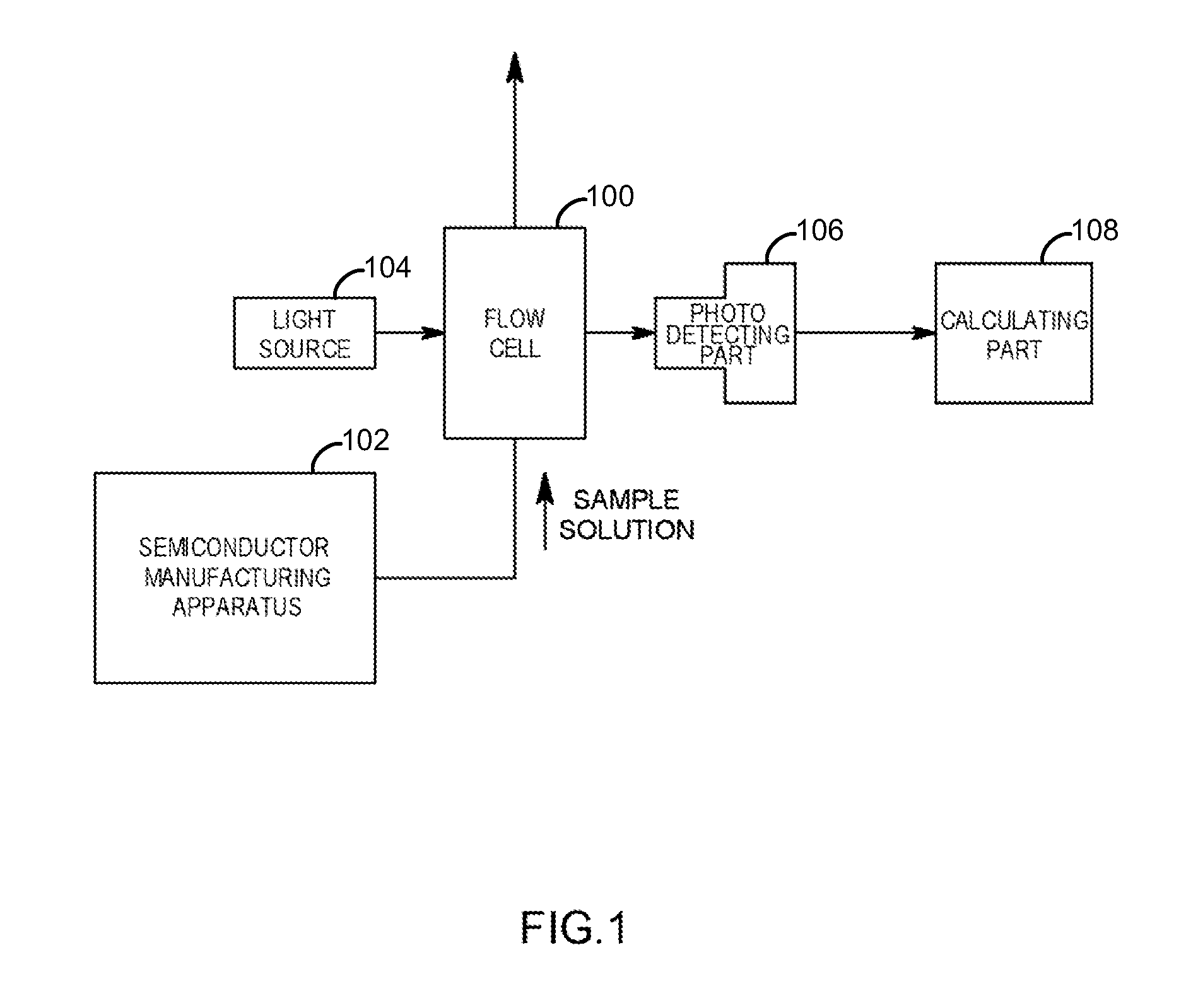
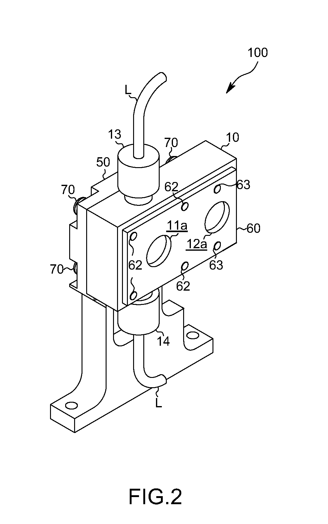
[0027]As shown in FIGS. 1-5, the optical measurement flow cell 100 pertaining to the present embodiment is connected to a pipe L provided in a semiconductor manufacturing apparatus 102 and it is used for measuring a concentration of a chemical solution (sample solution) such as hydrofluoric acid. The flow cell 100 includes a pair of optical windows 23 which are facing each other and sandwiching a flow channel in which the sample solution flows. The sample solution is irradiated with light emitted by a light source 104 through one of the optical windows 23, and a transmitted light outputted through the other optical window 23 is received by a photo detecting part 106. A calculating part 108 receives a light intensity signal from the photo detecting part 106 so that a concentration of a prescribed component contained in the samp...


PUM


Abstract

To make it possible to alter a cell length with reduction of a manufacturing cost so that a spacer can be securely positioned at a desired position, a cell includes: a pair of optical windows sandwiching a flow channel; a cell body provided with an accommodating recess and a solution introduction part and a solution deriving part; a pair of light transmitting members in the accommodating recess and forming the pair of optical windows; a spacer defining a distance between the opposing surfaces of the pair of light transmitting members; and a pressing mechanism for pressing the light transmitting members and the spacer toward the bottom surface of the accommodating recess so as to form the flow channel, wherein a positioning recess having a shape corresponding to the spacer is provided on at least one of the opposing surfaces and the spacer is fitted therein.

Description

TECHNICAL FIELD[0001]The present invention generally relates to an optical measurement cell for measuring a concentration of a chemical solution such as hydrofluoric acid (HF) in a manufacturing process of, e.g., a semiconductor and the like, and, in particular, to an optical measurement flow cell having a pair of optical windows sandwiching a flow channel therebetween for flowing a sample solution.BACKGROUND ART[0002]This type of flow cell is connected to a chemical solution pipe provided in a semiconductor manufacturing apparatus. A measurement light is irradiated to a sample solution through one of the optical windows of the flow cell and a transmitted light emitted from the other of the optical windows is received. Then, a concentration of a prescribed component contained in the sample solution is calculated based on a transmitted light intensity of the sample solution so that the concentration of the chemical solution is controlled.[0003]Regarding the conventional flow cell, as...

Claims


Application Information

Patent Timeline
IPC IPC(8): G01J1/00
CPCG01N21/05G01N2021/0346G01N2021/058G01N21/09H01L22/00G01J1/04
Inventor YOKOYAMA, ISSEIARIMOTO, KIMIHIKO
Owner HORIBA LTD
Learn More