
Vertical blind assembly

Active Publication Date: 2019-01-10
WONDERSHADES LLC
View PDF0 Cites 0 Cited by
  • Summary
  • Abstract
  • Description
  • Claims
  • Application Information

AI Technical Summary

Benefits of technology

The invention relates to an assembly of vertical slats that can be rotated, even when partially raised. The slats can be manually or using an electric motor. The assembly includes a plurality of layers that can be coupled together, and strips positioned within the slat component to provide rigidity and change the width or length of the shade. The overall width or length of the shade can be altered to the user's desire, and the shade can be lowered and raised by pulling and pushing the sheath or slat components.

Problems solved by technology

However, even when slats of the prior blinds are in their fully open position, they still occlude the window to some extent in that an observer sees the edges of the slats when looking out the window.
Some vertical blinds are also disadvantaged in that they are usually fabricated in relatively few widths to fit standard window sizes.
Therefore, they may not be suitable for windows that do not conform to those standards.

Method used


Image

  • Vertical blind assembly
  • Vertical blind assembly
  • Vertical blind assembly

Examples


Embodiment Construction

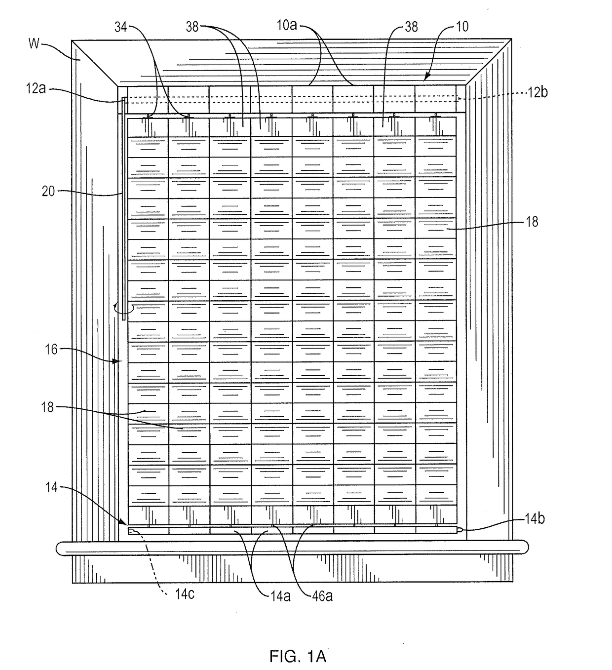
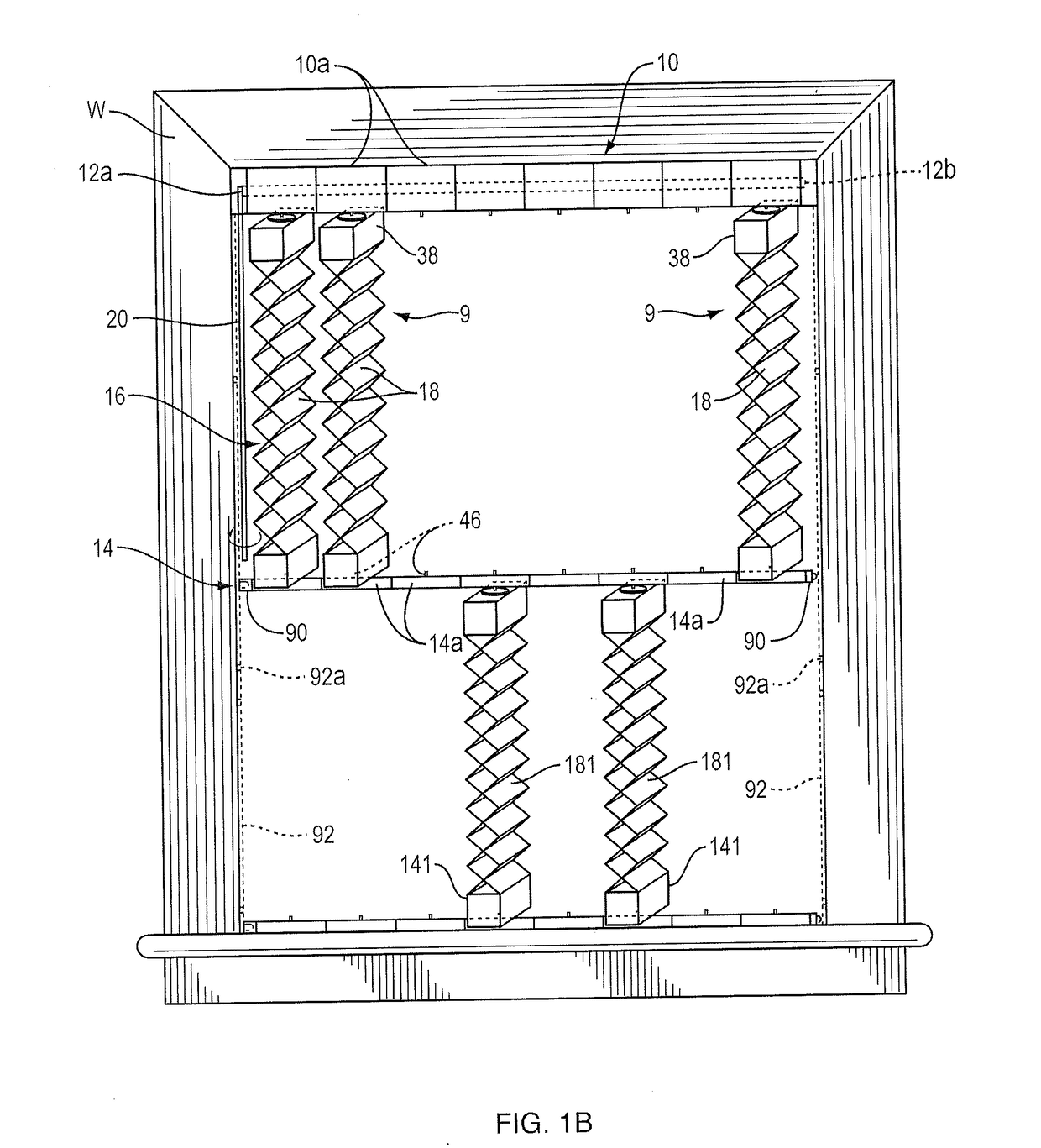
[0095]As shown in FIGS. 1A and 1B, my vertical blind assembly comprises a head rail 10 mounted at the top of a window W by means of brackets 12a and 12b which support the opposite ends of the head rail. The assembly also includes a foot rail shown generally at 14, and extending between the head rail and the foot rail is a window blind 16 comprised of a plurality of vertical slats or louvers 18. By pulling down or lifting up the foot rail 14, the blind 16 may be moved from a fully extended or lowered position shown in FIG. 1A to a partially retracted or raised position shown in FIG. 1B and then to a fully raised or retracted position, not shown, wherein the foot rail 14 lies just under the head rail 10 so that the blind 16 does not obstruct the view through the window. Furthermore, by turning a wand 20 in one direction or the other, the slats 18 of blind 16 can be rotated about their vertical axes from a fully closed position as shown in FIG. 1A wherein the slats lie parallel to the ...


PUM


Abstract

A modular shade includes at least one module that consists of a head rail unit, a foot rail unit, at least one intermediate rail unit, and a plurality of slat components. A top slat may be coupled to the head rail unit and the intermediate rail unit, and a bottom slat component may be coupled to the intermediate rail unit and the foot rail unit. Further, additional intermediate rail units and intermediate slat components may be added to the module to alter the shape and size of the module, and the module may be coupled to one or more additional modules to change the overall shape and size of the modular shade.

Description

CROSS-REFERENCE TO RELATED APPLICATION[0001]The present application is a continuation in part application of U.S. patent application Ser. No. 15 / 712,931 filed Sep. 22, 2017, which is a continuation in part application of U.S. patent application Ser. No. 15 / 348,416, filed Nov. 10, 2016, now patented as U.S. Pat. No. 10,030,437 on Jul. 24, 2018, which is a continuation in part application of U.S. patent application Ser. No. 15 / 228,429, filed Aug. 4, 2016 which is continuation in part application of U.S. patent application Ser. No. 15 / 062,900, filed Mar. 7, 2016, now patented as U.S. Pat. No. 9,739,087 on Aug. 22, 2017, which is a continuation in part application of U.S. patent application Ser. No. 14 / 932,300, filed Nov. 4, 2015, now patented as U.S. Pat. No. 9,732,554 on Aug. 15, 2017, which is a continuation in part application of U.S. patent application Ser. No. 14 / 489,002, filed Sep. 17, 2014, now patented as U.S. Pat. No. 9,260,913 on Feb. 16, 2016, which is a continuation in part...

Claims


Application Information

Patent Timeline
IPC IPC(8): E06B9/262E06B9/386E06B9/322E06B9/382
CPCE06B9/262E06B9/386E06B2009/2627E06B9/382E06B2009/2622E06B9/322E06B9/362E06B9/364E06B9/367E06B9/368E06B9/388E06B2009/2447E06B2009/2625E06B9/42E06B2009/2488
Inventor TEUSCHER, JASON B.
Owner WONDERSHADES LLC
Learn More