
Preloaded dual-spring assembly

a dual-spring, preloaded technology, applied in the direction of spring/damper functional characteristics, shock absorbers, wound springs, etc., can solve the problems of not adjustable, efficiency and operation of shock absorbers, and achieve the effect of high spring ra

Inactive Publication Date: 2011-12-01
RENTON COIL SPRING
View PDF9 Cites 30 Cited by
  • Summary
  • Abstract
  • Description
  • Claims
  • Application Information

AI Technical Summary

Benefits of technology

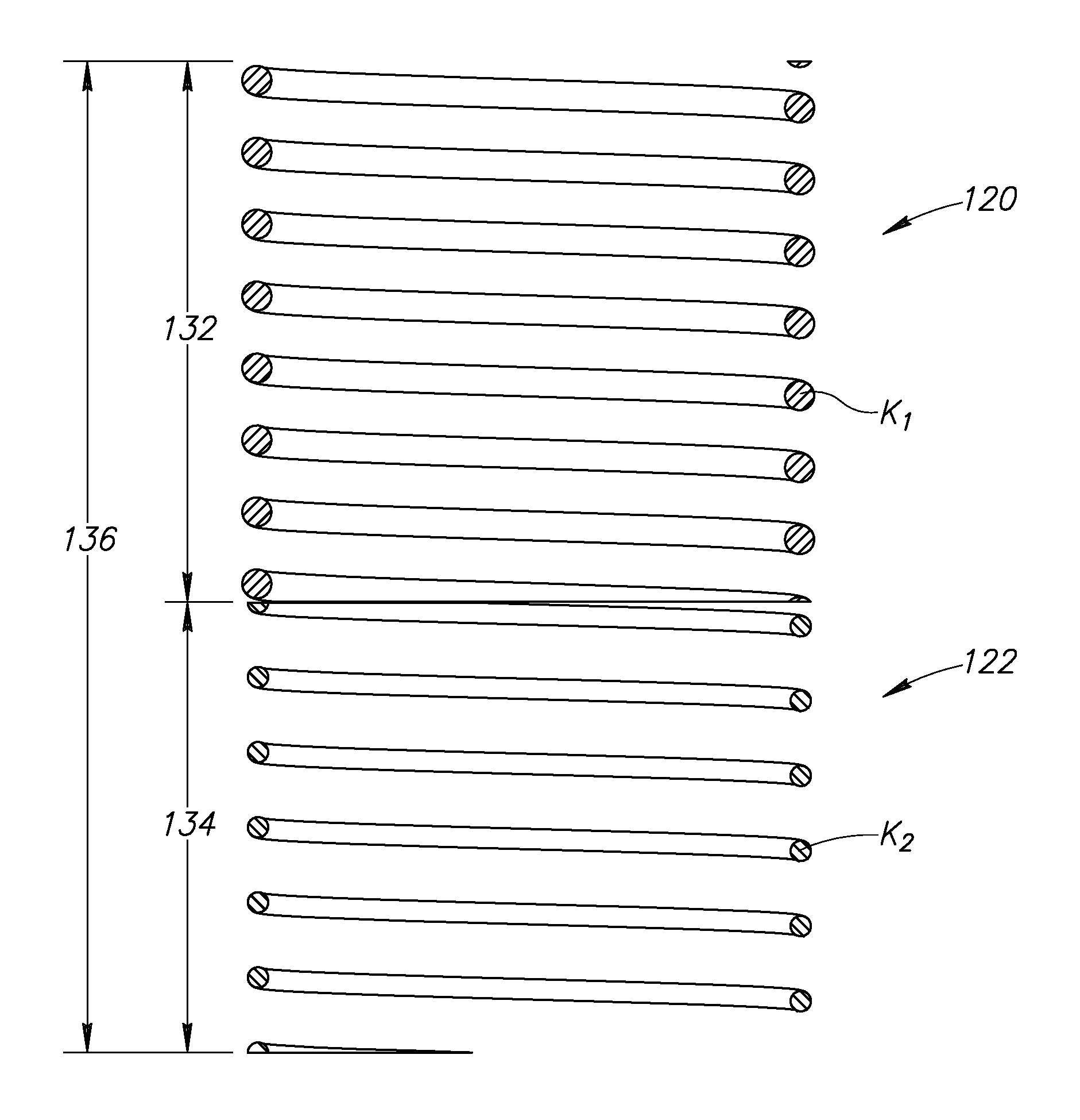
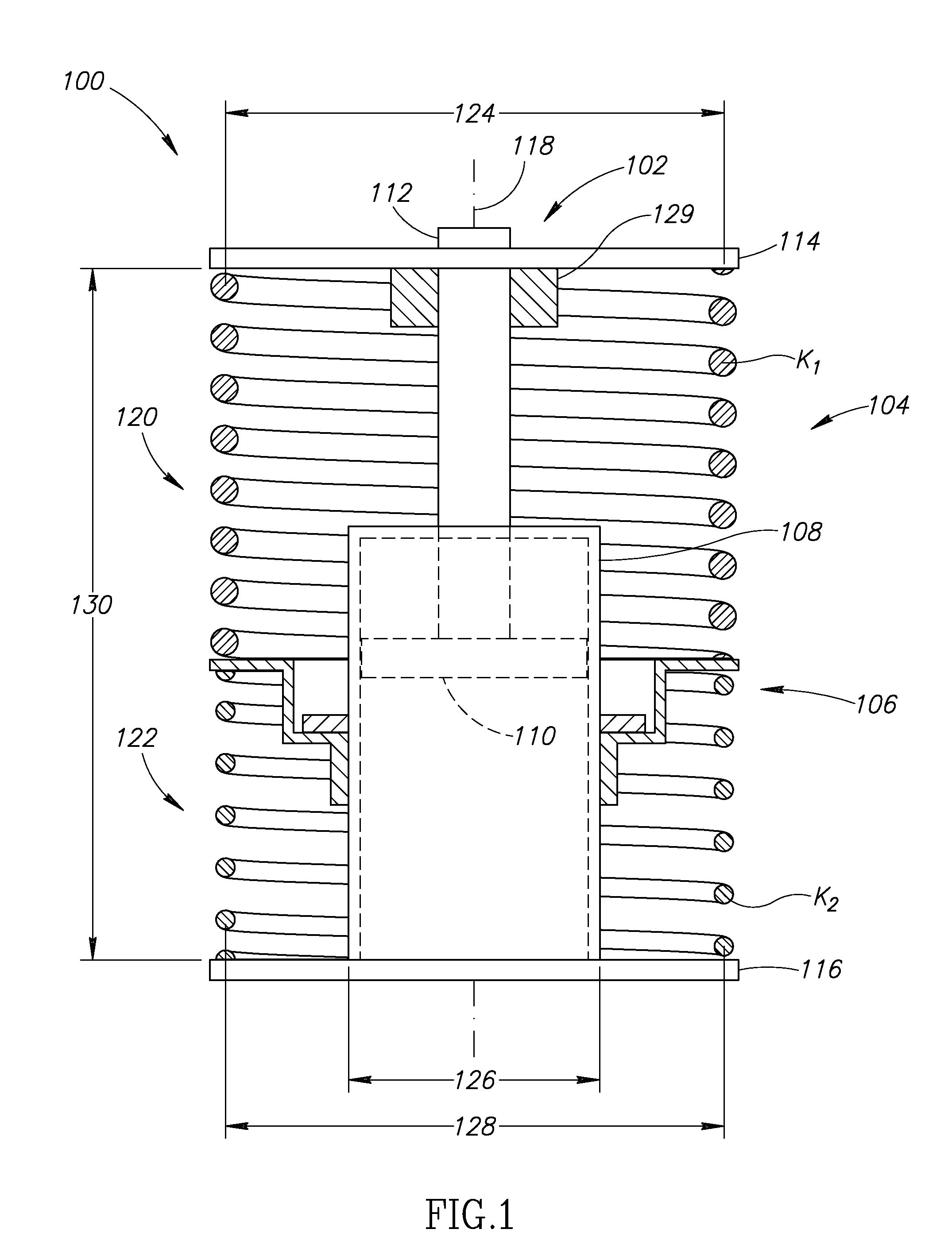
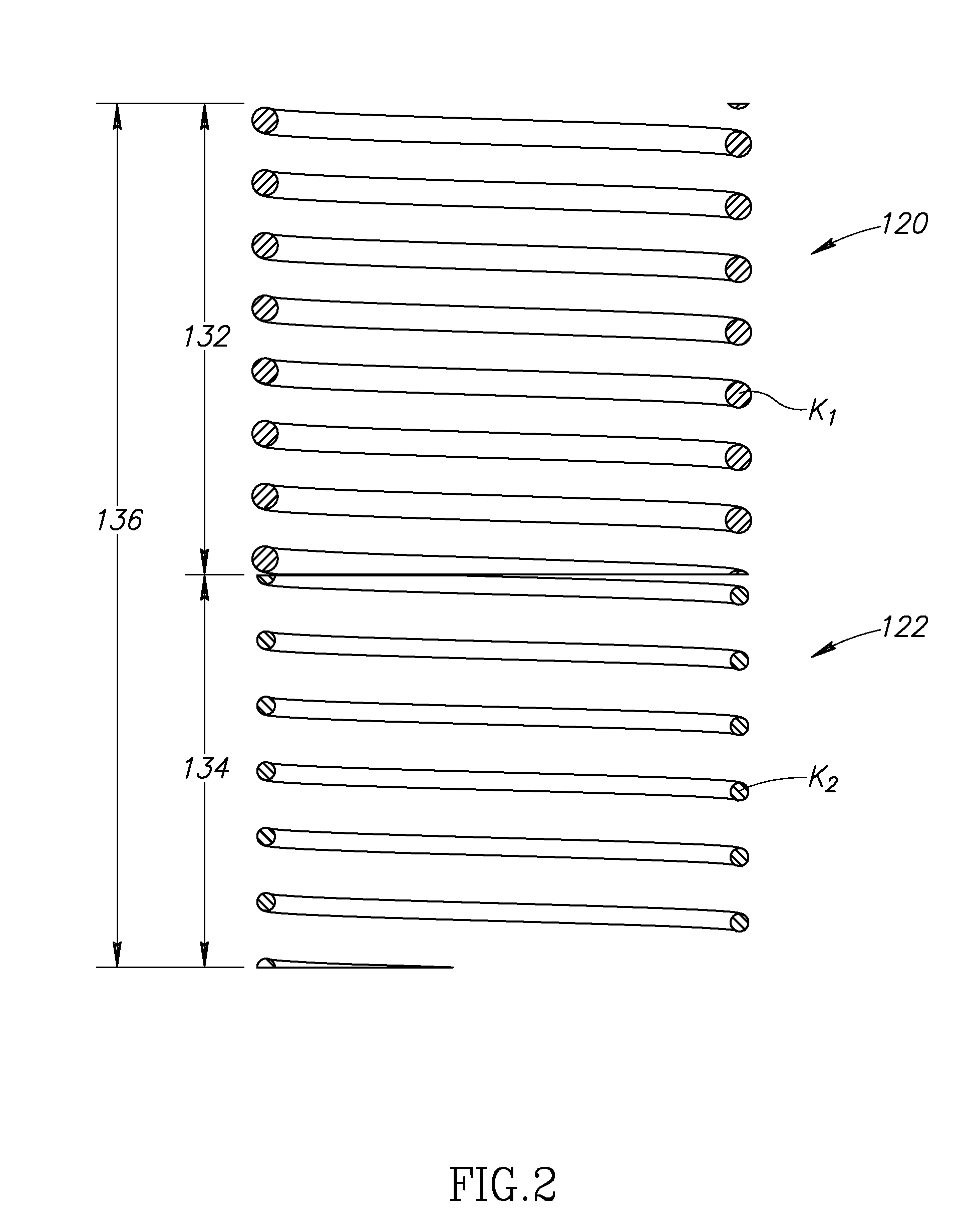
[0005]In accordance with an aspect of the invention, a dual-spring assembly for a shock absorber includes a first compression spring having a first spring rate; and a second compression spring having a second spring rate that may be lower, higher, or the same as the first spring rate, the second compression spring having an amount of preload, the first and second compression springs arranged in series and operable to have an effective spring rate for absorbing energy from an applied load after the applied load is large enough to overcome the amount of preload in the second compression spring. The combined effective spring rate of the springs, once the preload is overcome (i.e., both springs engaged) is lower than the spring rate of the first spring. This lower effective spring rate allows the vehicle to better deal with high amplitude impact occurrences that would otherwise be very disruptive to a completely progressive suspension with a high spring rate.

Problems solved by technology

Typically, the damping coefficient of the shock damper and the spring constant of a compression spring are often fixed and thus not adjustable once the shock absorber has been fully assembled.
However, one or more of the following may affect the efficiency and operation of the shock absorber: the vehicle weight, the range of driving speeds, the terrain (e.g., uneven or rough terrain), steering requirements and the environment.

Method used


Image

  • Preloaded dual-spring assembly
  • Preloaded dual-spring assembly
  • Preloaded dual-spring assembly

Examples


Embodiment Construction

[0014]As will be described in further detail below, at least one embodiment of the invention includes a dual-spring assembly that may cooperate with a damper unit of a shock absorber. In addition, the shock absorber may include a preload system for preloading at least one of the springs. The dual springs are arranged in series. In one embodiment, the spring with the higher spring rate operates as the primary spring to absorb the energy from applied loads that are less than a desired amplitude of applied load. For loads greater than the desired amplitude of applied load and after the preload in the second spring has been overcome, the springs operate together with a lower effective spring rate to absorb high amplitude impact loads, for example. In another embodiment, the spring with the lower individual spring rate operates as the primary spring, with the higher rate spring being preloaded. However, even in this embodiment, the combined effective spring rate, once the preload is over...


PUM


Abstract

The present invention relates to dual-spring assembly that may be employed in cooperation with a damper unit to form a shock absorber. The spring rate of at least one of the springs is adjustable with a preload mechanism, which in turn is movable relative to the damper unit. Further, the dual-spring assembly includes two compression springs arranged in series and each having selected, but different spring rates. The first spring primarily absorbs the energy of applied loads that are below a first amplitude or threshold of applied load. Once the applied loads exceed the first amplitude of applied load, the dual-spring assembly operates with an effective spring rate to absorb the energy of applied loads that exceed the first amplitude of applied load. After a second spring of the dual-spring assembly achieves a desired amount of deflection, the first spring continues to absorb energy from the applied loads.

Description

FIELD OF THE INVENTION[0001]This invention relates generally to a dual-spring assembly for varying the combined resultant spring rate of the assembly as the dual springs are compressed, and more specifically to a shock absorber unit having the dual-spring assembly with a system for adjusting an amount of preload in one or both of the springs.BACKGROUND OF THE INVENTION[0002]Conventional shock absorbers of the type used in vehicles, such as automobiles, typically include a shock damper and a compression spring. At least two parameters considered when designing shock absorbers include the weight of the vehicle and the probable range of driving speeds. Typically, the damping coefficient of the shock damper and the spring constant of a compression spring are often fixed and thus not adjustable once the shock absorber has been fully assembled. However, one or more of the following may affect the efficiency and operation of the shock absorber: the vehicle weight, the range of driving spee...

Claims


Application Information

Patent Timeline
Patent Type & Authority Applications(United States)
IPC IPC(8): B60G15/06B60G15/07F16F3/04
CPCF16F3/04F16F2228/08B60G11/48B60G11/14B60G11/32B60G7/04
Inventor PEPKA, CHARLES F.
Owner RENTON COIL SPRING
Learn More