
Frequency jitter controller for power converter

Active Publication Date: 2011-11-24
POWER FOREST TECH
View PDF10 Cites 9 Cited by
  • Summary
  • Abstract
  • Description
  • Claims
  • Application Information

AI Technical Summary

Benefits of technology

[0008]The disclosure is directed to a frequency jitter controller for a power converter, which can reduce electromagnetic interference (EMI) generated by switching switch-elements in the power converter.
[0018]In an exemplary embodiment of the disclosure, a voltage value of the crossing-voltage is decreased as the capacitance of the second capacitance unit is increased. Conversely, the voltage value of the crossing-voltage is increased as the capacitance of the second capacitance unit is decreased.
[0022]In an embodiment of the invention, a voltage value of the crossing-voltage is increased as the charging current of the second capacitance unit is increased. Conversely, the voltage value of the crossing-voltage is decreased as the charging current of the second capacitance unit is decreased.
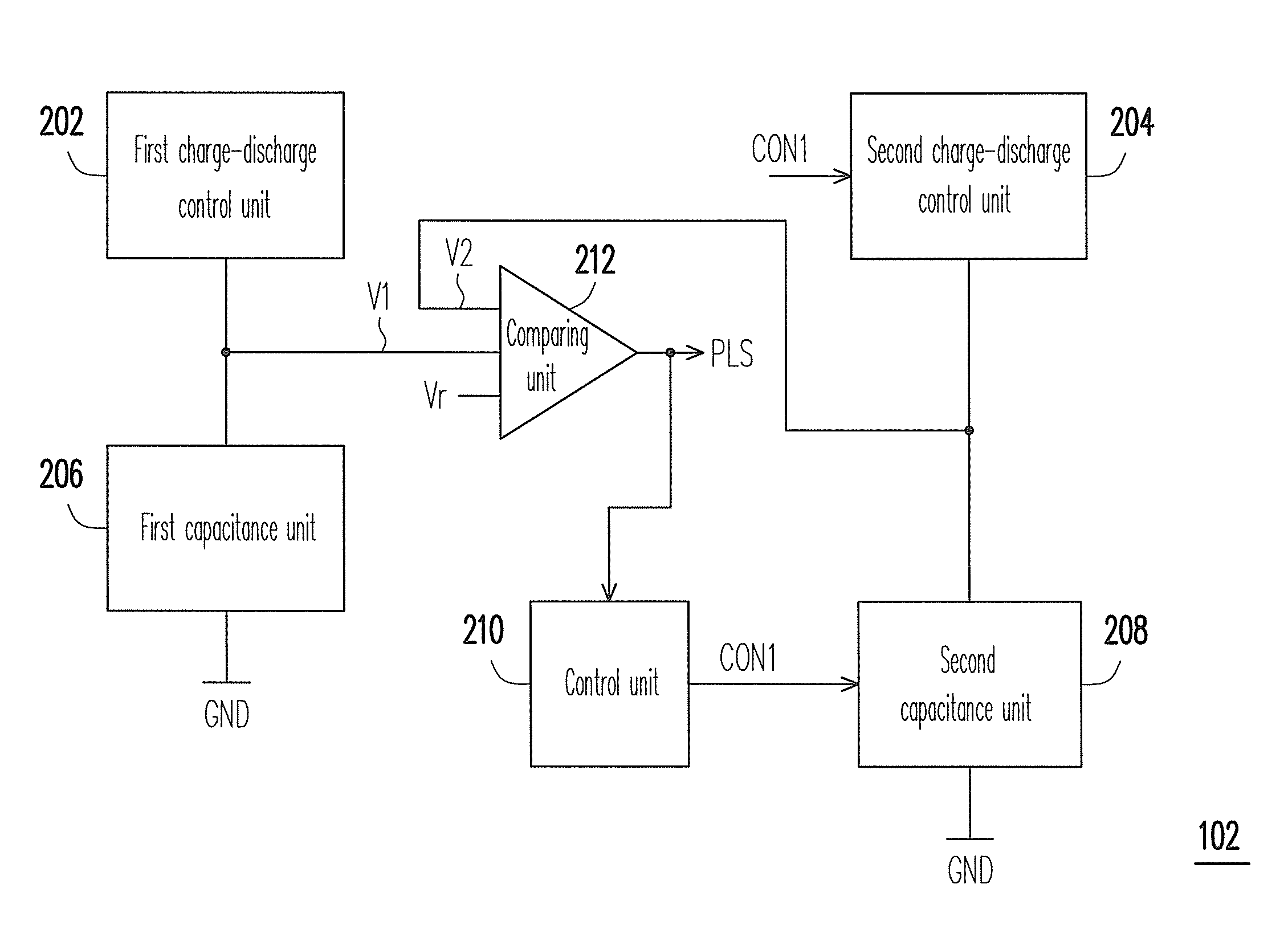
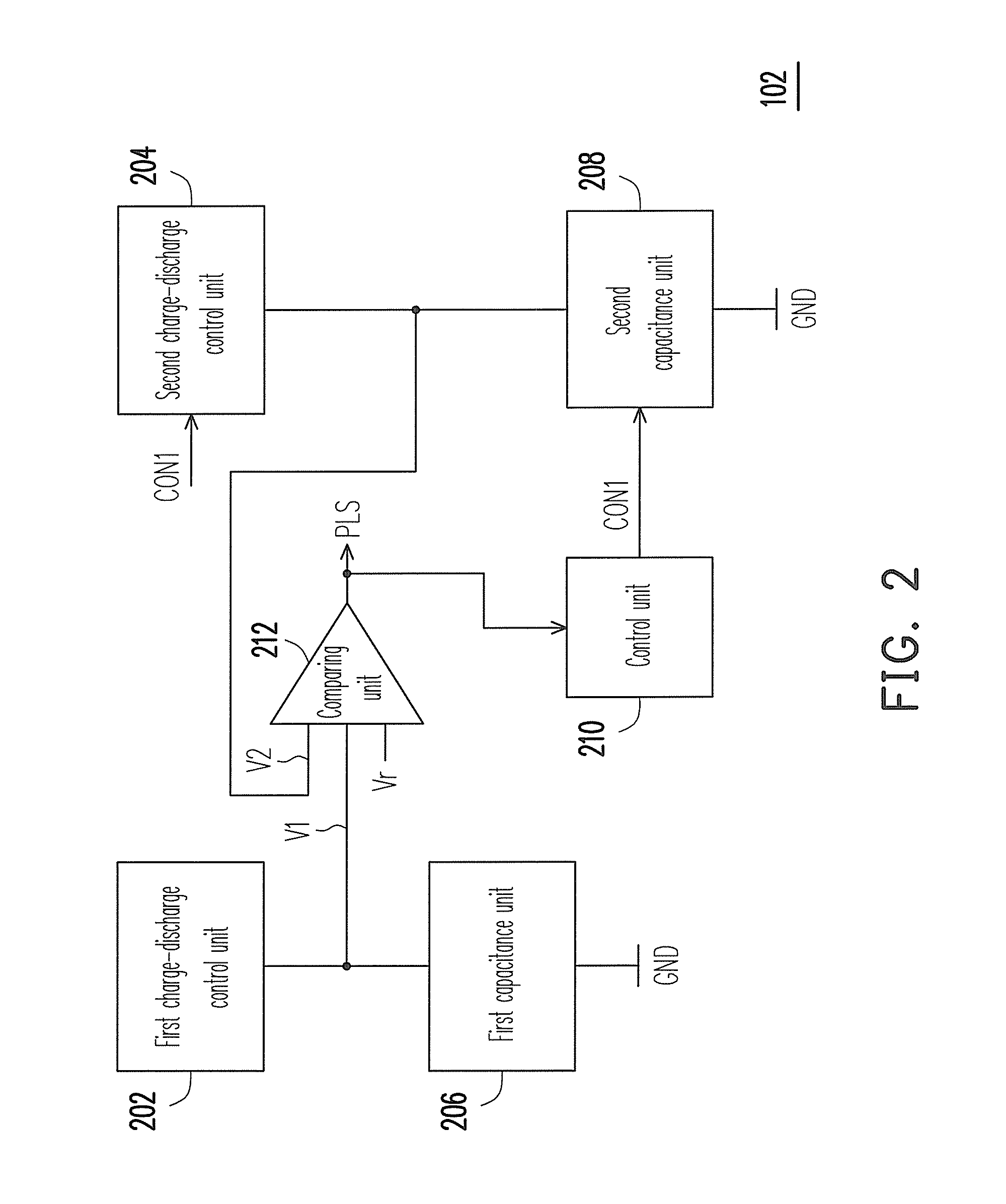
[0024]According to the above descriptions, the frequency jitter control signal output by the control unit of the frequency jitter controller is used to adjust the rising rate of the voltage on the second capacitance unit, so as to change a charging rate of the second capacitance unit, and accordingly advance or postpone a transition time of the pulse signal output by the comparing unit. In this way, the frequency of the pulse signal can be changed, so that a switching frequency can be spread in a relatively great bandwidth, so as to reduce the EMI generated by switching switch-elements in the power converter.

Problems solved by technology

However, the EMI generated by the switching power converter can cause a noise of the power supply to influence other electronic devices, and can also influence signal transmissions of the neighboring communication devices or radios and televisions due to an outgoing radiation.
However, the greater the EMI is, the greater the required EMI filter is, so that not only a circuit cost is increased, but also the EMI filter cannot deal with the radiation of the EMI.

Method used


Image

  • Frequency jitter controller for power converter
  • Frequency jitter controller for power converter
  • Frequency jitter controller for power converter

Examples


Embodiment Construction

[0034]Reference will now be made in detail to the present preferred embodiments of the disclosure, examples of which are illustrated in the accompanying drawings. Wherever possible, the same reference numbers are used in the drawings and the description to refer to the same or like parts.

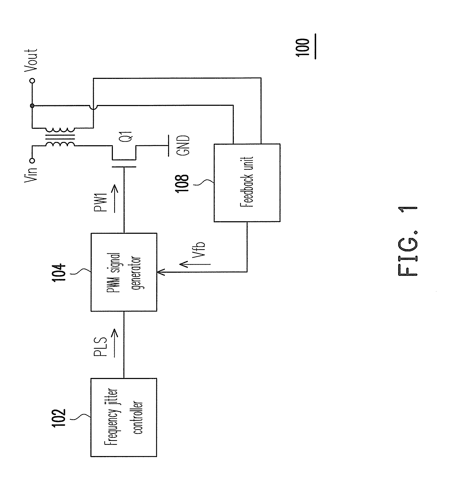
[0035]FIG. 1 is a schematic diagram illustrating a power converter according to an exemplary embodiment of the disclosure. Referring to FIG. 1, the power converter 100 is used for converting an unregulated power into a regulated voltage or current, for example, converting an input voltage Vin of FIG. 1 into a regulated output voltage Vout. The power converter 100 includes a frequency jitter controller 102, a pulse width modulation (PWM) signal generator 104, a transformer 106, a feedback unit 108 and a transistor Q1. Wherein, the PWM signal generator 104 is coupled between a gate of the transistor Q1 and the frequency jitter controller 102, the transistor Q1 is coupled between a primary side of the ...


PUM


Abstract

A frequency-jitter-controller for a power-converter is provided, and which includes a first and a second capacitance units, a first and a second charge-discharge control units, a comparing unit and a control unit. Both capacitance units are charged to a crossing-voltage during a charging phase and discharged to a reference voltage and a clamp voltage respectively during a discharging-phase in response to operations of both charge-discharge control units. The comparing unit outputs a pulse signal, compares voltages of both capacitance units during the charging phase, and compares the voltage of the first capacitance unit and the reference voltage during the discharging phase. The control unit generates a frequency jitter control signal according to the pulse signal to adjust a rising rate of the voltage on the second capacitance unit, so as to change a frequency of the pulse signal, and thus reduce EMI generated by switching switch-elements in the power-converter.

Description

CROSS-REFERENCE TO RELATED APPLICATION[0001]This application claims the priority benefit of Taiwan application serial no. 99116311, filed on May 21, 2010. The entirety of the above-mentioned patent application is hereby incorporated by reference herein and made a part of specification.BACKGROUND[0002]1. Field of the Disclosure[0003]The disclosure relates to a power converter, more particularly, to a power converter having a low electromagnetic interference (EMI).[0004]2. Description of Related Art[0005]A power converter is used for converting unregulated power into a regulated voltage or current. Generally, a control circuit in the power converter can generate a switch signal to regulate an output voltage or current of the power converter, so as to adjust and stabilize the power of the power converter. Wherein, a duty cycle of the switch signal is modulated according to the output of the power converter, and a switching frequency of the switch signal is generally self-determined in ...

Claims


Application Information

Patent Timeline
IPC IPC(8): H03K7/08
CPCH03K7/08H03K3/84
Inventor CHIA, JU-LIN
Owner POWER FOREST TECH
Learn More