Moving image encoding apparatus and method of controlling the same

Inactive Publication Date: 2011-11-17
CANON KK
View PDF8 Cites 9 Cited by
  • Summary
  • Abstract
  • Description
  • Claims
  • Application Information

AI Technical Summary

Benefits of technology

[0011]The present invention has been made in consideration of the above-described situation, and provides a technique of selecting a motion vector in motion compensation prediction encoding so as to suppress image quality degradation in a moving image including a small change.
[0012]According to a first aspect of the present invention, there is provided a moving image encoding apparatus for performing motion compensation prediction encoding for an encoding target block image existing at a predetermined position of an encoding target image using one motion vector selected from a plurality of motion vectors serving as candidates, comprising: a calculation unit configured to calculate, for each of the plurality of motion vectors, a difference between the encoding target block image and a reference block image which exists at a position moved based on the motion vector from a position in a reference image corresponding to the predetermined position; a selection unit configured to select one motion vector from the plurality of motion vectors such that reducing a code amount when the selected motion vector is encoded and reducing the difference corresponding to the selected motion vector are achieved in predetermined balance; and an encoding unit configured to encode the motion vector selected by the selection unit and the difference calculated for the motion vector by the calculation unit, wherein the predetermined balance gives priority to reducing the difference over reducing the code amount as a minimum value of a plurality of differences calculated by the calculation unit becomes smaller, and gives priority to reducing the code amount over reducing the difference as the minimum value becomes larger.
[0013]According to a second aspect of the present invention, there is provided a moving image encoding apparatus for performing motion compensation prediction encoding for an encoding target block image existing at a predetermined position of an encoding target image using one motion vector selected from a plurality of motion vectors serving as candidates, comprising: a first calculation unit configured to, for each of the plurality of motion vectors, reduce the encoding target block image and a reference block image which exists at a position moved based on the motion vector from a position in a reference image corresponding to the predetermined position and calculate a difference between the reduced block image and the reduced reference block image; a first selection unit configured to select one motion vector from the plurality of motion vectors such that reducing a code amount when the selected motion vector is encoded and reducing the difference corresponding to the selected motion vector are achieved in first balance; a second calculation unit configured to calculate, for, out of the plurality of motion vectors, each of the motion vectors whose distances from a position indicated by the motion vector selected by the first selection unit are equal to or smaller than a threshold, a difference between the block image and the reference block image; a second selection unit configured to select one motion vector from the motion vectors whose distances from the position indicated by the motion vector selected by the first selection unit are equal to or smaller than the threshold such that reducing the code amount when the selected motion vector is encoded and reducing the difference corresponding to the selected motion vector are achieved in second balance; and an encoding unit configured to encode the motion vector selected by the second selection unit and the difference calculated for the motion vector by the second calculation unit, wherein the first balance gives priority to reducing the difference over reducing the code amount as a minimum value of a plurality of differences calculated by the first calculation unit becomes smaller, and gives priority to reducing the code amount over reducing the difference as the minimum value becomes larger.
[0014]According to a third aspect of the present invention, there is provided a method of controlling a moving image encoding apparatus for performing motion compensation prediction encoding for an encoding target block image existing at a predetermined position of an encoding target image using one motion vector selected from a plurality of motion vectors serving as candidates, comprising: a calculation step of calculating, for each of the plurality of motion vectors, a difference between the encoding target block image and a reference block image which exists at a position moved based on the motion vector from a position in a reference image corresponding to the predetermined position; a selection step of selecting one motion vector from the plurality of motion vectors such that reducing a code amount when the selected motion vector is encoded and reducing the difference corresponding to the selected motion vector are achieved in predetermined balance; and an encoding step of encoding the motion vector selected in the selection step and the difference calculated for the motion vector in the calculation step, wherein the predetermined balance gives priority to reducing the difference over reducing the code amount as a minimum value of a plurality of differences calculated in the calculation step becomes smaller, and gives priority to reducing the code amount over reducing the difference as the minimum value becomes larger.
[0016]With the above-described arrangement, according to the present invention, it is possible to select a motion vector in motion compensation prediction encoding so as to suppress image quality degradation in a moving image including a small change.

Problems solved by technology

Therefore, when the motion vectors of a plurality of macroblocks are to be searched for in parallel, it may be impossible to correctly calculate the code amount R of a motion vector because the motion vector of a peripheral macroblock has not yet been selected.
That is, a motion vector different from that closest to the actual motion (change) in the moving image may be selected, resulting in degradation in the quality of the encoded moving image.
In general, the image quality degradation is not so clearly visually recognized.
However, in a moving image with a small change (for example, a moving image that shows cloud in the blue sky moves while maintaining its shape), the image quality degradation is readily visually recognized (for example, the afterimage of cloud is recognized in the decoded image).
As a result, a motion vector that is not so close to the actual motion of the moving image may be selected even for a moving image whose image quality degradation is readily recognized, and user satisfaction for the image quality may lower.

Method used


Image

  • Moving image encoding apparatus and method of controlling the same
  • Moving image encoding apparatus and method of controlling the same
  • Moving image encoding apparatus and method of controlling the same

Examples


first embodiment

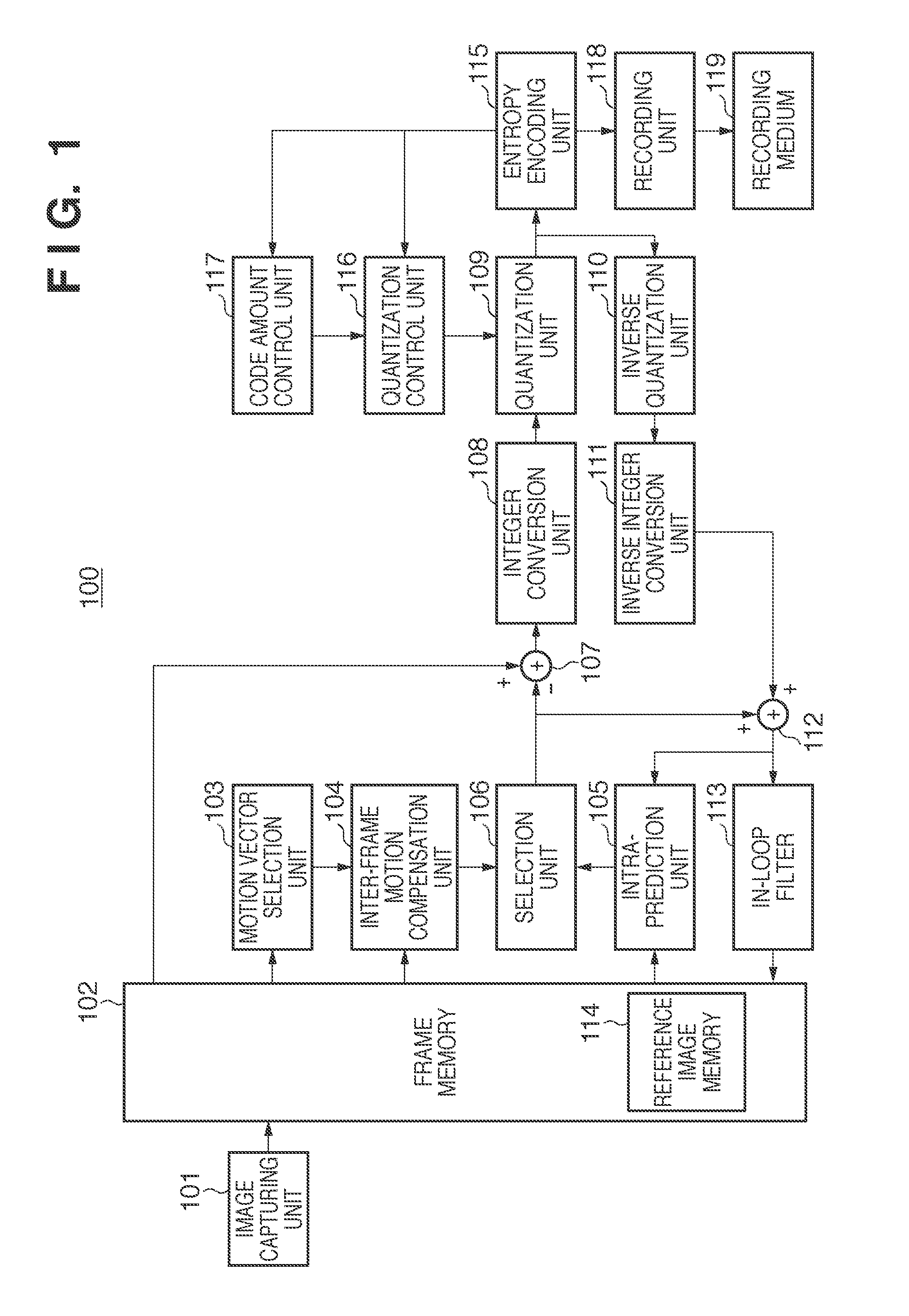
[0026]FIG. 1 is a block diagram showing an example of the arrangement of a moving image encoding apparatus 100 according to the embodiment. The apparatus includes: an image capturing unit 101 including a camera unit with a lens, an image sensor, and the like; a frame memory 102; a motion vector selection unit 103 that searches for motion vectors; and an inter-frame motion compensation unit 104 that generates inter-predicted image data based on the motion vectors. The apparatus also includes an intra-prediction unit 105 that generates intra-predicted image data, a selection unit 106 that selects one of the inter-predicted image data and the intra-predicted image data, a subtracter 107, an integer conversion unit 108, and a quantization unit 109. The apparatus also includes an inverse quantization unit 110, an inverse integer conversion unit 111, an adder 112, an in-loop filter 113, an entropy encoding unit 115, a quantization control unit 116, a code amount control unit 117, and a re...

second embodiment

[0061]In the second embodiment, the feature amount of an encoding target block image is used to decide a coefficient λ. The second embodiment is the same as the first embodiment except that the processing shown in FIG. 3 is replaced with processing shown in FIG. 5. The second embodiment will be described below with reference to FIG. 5. The same step numbers as in FIG. 3 denote the same or similar processes in FIG. 5, and a description thereof will not be repeated.

[0062]In step S510, a motion vector selection unit 103 detects the feature amount of an encoding target block image. The feature amount represents the degree of variation between the pixels of the encoding target block image. In this embodiment, a variance is used as the feature amount. Alternatively, the average value, dynamic range, or the like of luminance values may be used. In step S511, the motion vector selection unit 103 decides the value of a threshold Th1 based on the variance.

[0063]The variance used as the featur...

third embodiment

[0065]In the third embodiment, an arrangement that speeds up motion vector selection by parallelizing some processes will be described.

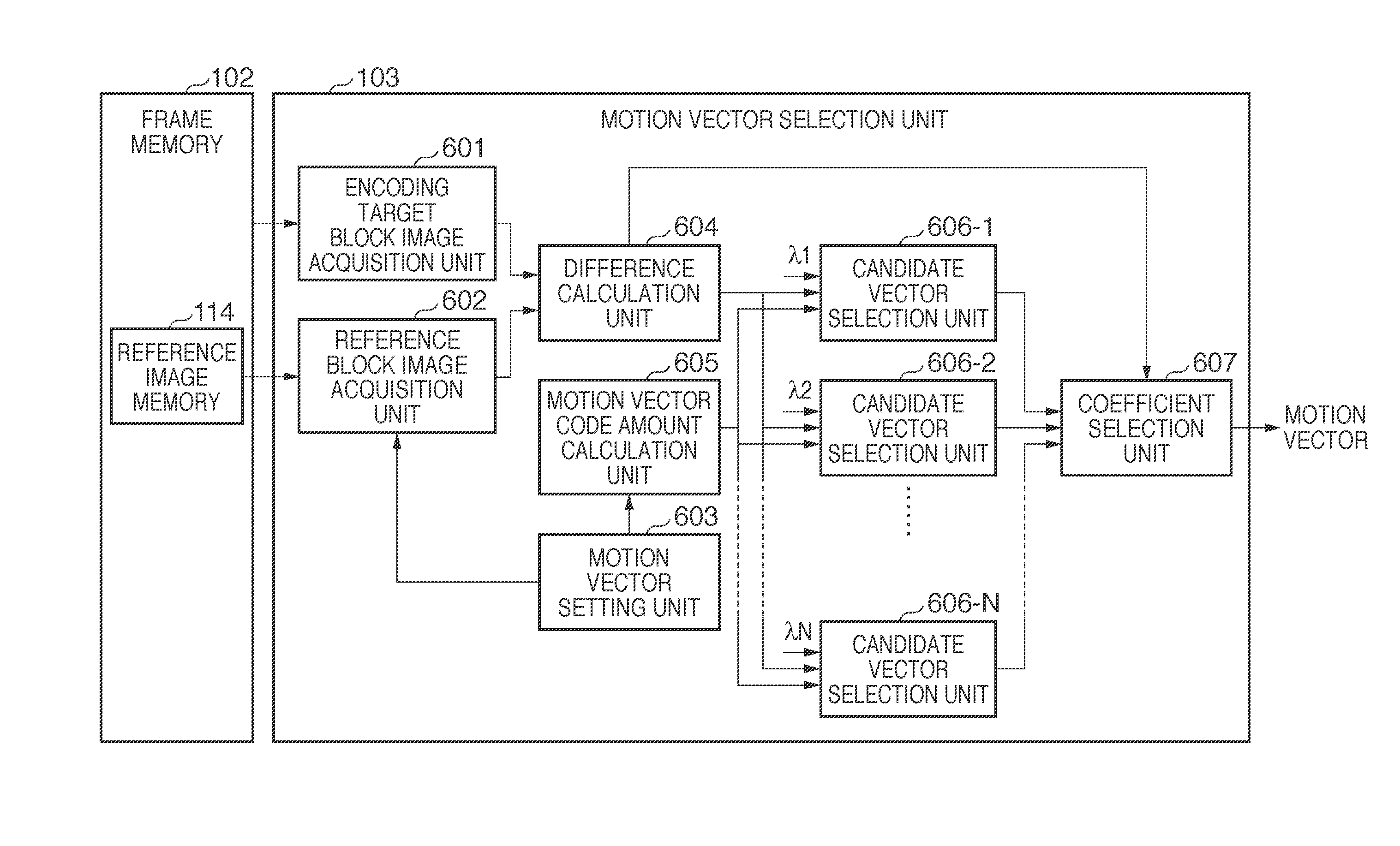
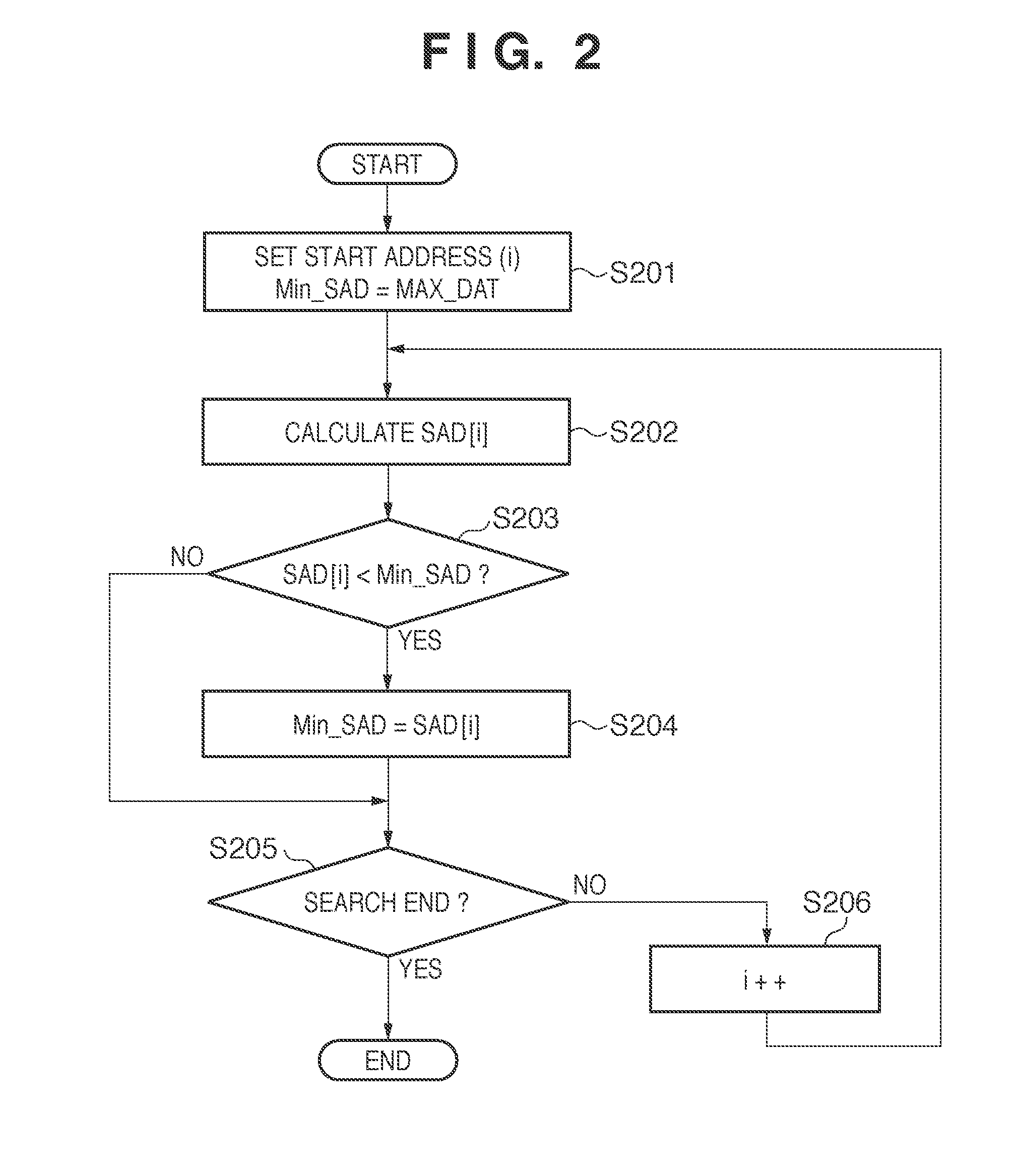
[0066]FIG. 6 is a block diagram showing the arrangement of a motion vector selection unit 103 according to the third embodiment. Referring to FIG. 6, an encoding target block image acquisition unit 601, a reference block image acquisition unit 602, a motion vector setting unit 603, and a difference calculation unit 604 calculate SAD for each of a plurality of motion vectors, as in the first embodiment (see FIG. 2).

[0067]More specifically, the encoding target block image acquisition unit 601 acquires an encoding target block image from a frame memory 102. The reference block image acquisition unit 602 acquires a reference block image from a reference image memory 114 in accordance with a motion vector set by the motion vector setting unit 603. The motion vector setting unit 603 sequentially sets, in the reference block image acquisition unit 602, each...


PUM


Abstract

There is provided a moving image encoding apparatus for performing motion compensation prediction encoding. The apparatus comprises, among other things: a calculation unit configured to calculate, for each of a plurality of motion vectors, a difference between an encoding target block image and a reference block image which exists at a position moved based on the motion vector from a position in a reference image corresponding to the predetermined position; and a selection unit configured to select one motion vector from the plurality of motion vectors such that reducing a code amount when the selected motion vector is encoded and reducing the difference corresponding to the selected motion vector are achieved in predetermined balance. The predetermined balance gives priority to reducing the difference over reducing the code amount as a minimum value of a plurality of differences calculated by the calculation unit becomes smaller.

Description

BACKGROUND OF THE INVENTION[0001]1. Field of the Invention[0002]The present invention relates to a moving image encoding apparatus and a method of controlling the same.[0003]2. Description of the Related Art[0004]A digital video camera is conventionally known well as a moving image encoding apparatus which captures an object image and compress-codes and records the moving image data obtained by image capturing. In recent years, a recording medium to be used to record moving image data is shifting from a conventional magnetic tape to a disk medium or semiconductor memory having high convenience such as random accessibility. MPEG-2 has become popular as the encoding method, which can compress moving image data at a high compression ratio by encoding using inter-frame motion prediction (motion compensation prediction encoding). H.264 capable of compressing moving image data at a higher compression ratio is also used recently.[0005]The moving image encoding apparatus for performing moti...

Claims


Application Information

Patent Timeline
IPC IPC(8): H04N7/32H04N19/50H04N19/105H04N19/134H04N19/137H04N19/139H04N19/14H04N19/196H04N19/423H04N19/46H04N19/503H04N19/51H04N19/513H04N19/533H04N19/567H04N19/593H04N19/60H04N19/61H04N19/70H04N19/82H04N19/85H04N19/91
CPCH04N19/567H04N19/61
Inventor OISHI, AKIHIROENDO, HIROAKI
Owner CANON KK
Why Eureka
Try Eureka