Radiological image radiographing device, radiation image radiographing system, and radiation image radiographing method
a radiographing device and radiographing technology, applied in the direction of optical radiation measurement, material analysis using wave/particle radiation, instruments, etc., can solve problems such as image quality degradation, and achieve the effect of suppressing image quality degradation
- Summary
- Abstract
- Description
- Claims
- Application Information
AI Technical Summary
Benefits of technology
Problems solved by technology
Method used
Image

Examples
first embodiment
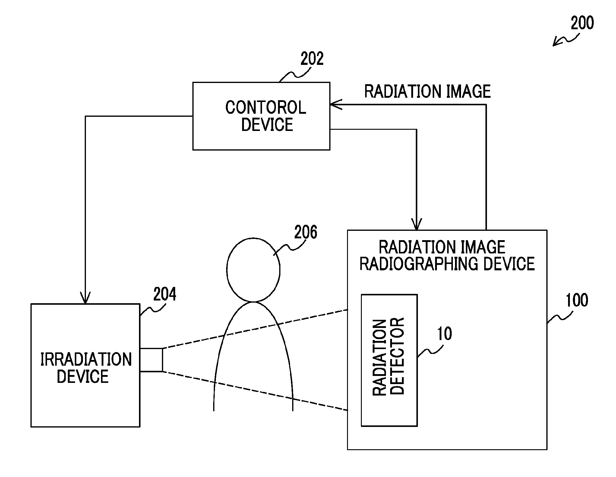
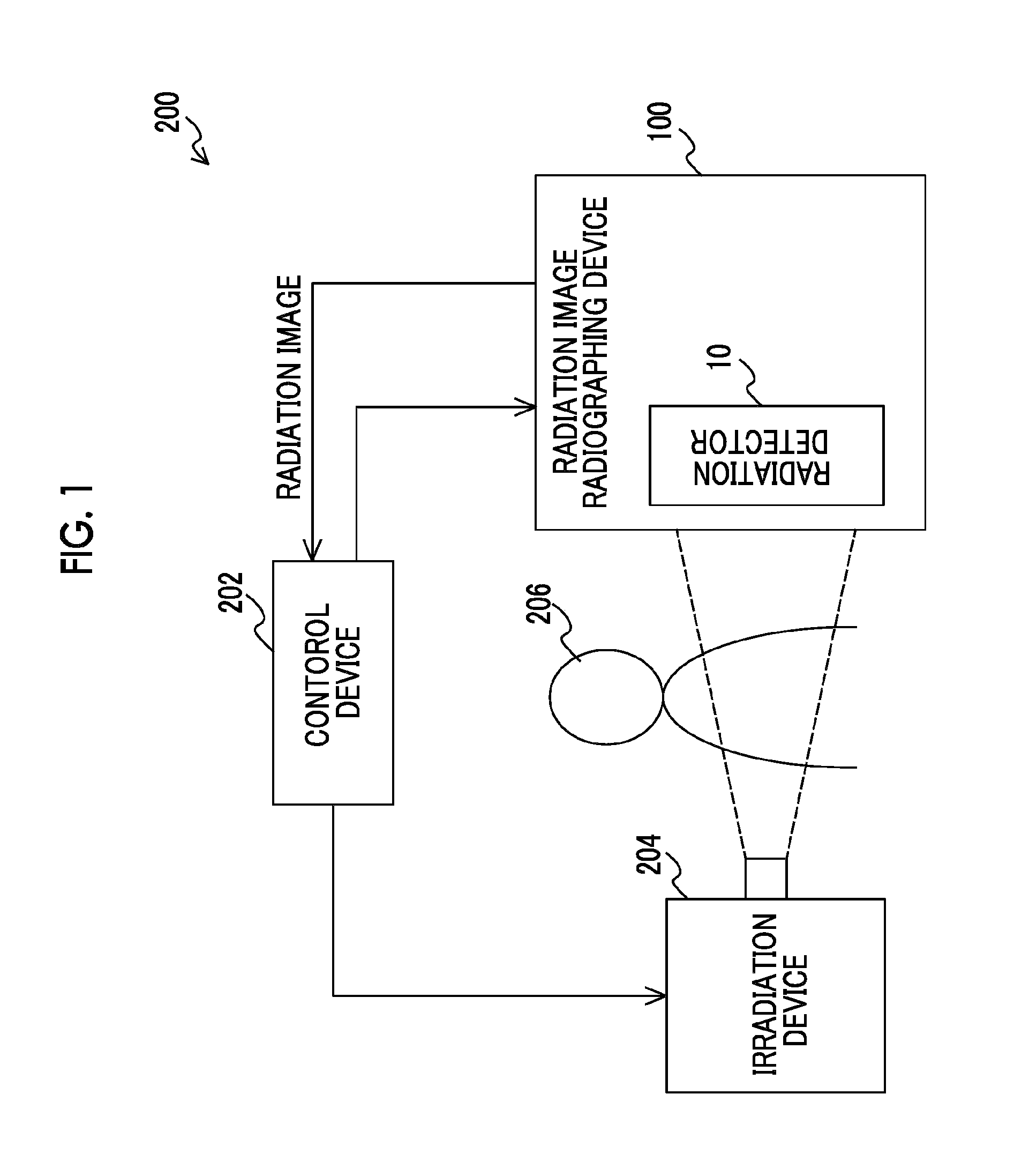
[0039]First, the schematic configuration of a radiological image radiographing system using a radiological image radiographing device of this embodiment will be described. FIG. 1 is a schematic configuration diagram of an example of a radiological image radiographing system of this embodiment.
[0040]A radiological image radiographing system 200 includes an irradiation device 204 which irradiates a radiation (for example, X-ray or the like) onto a subject 206, a radiological image radiographing device 100 including a radiation detector 10 which detects the radiation irradiated from the irradiation device 204 and transmitting the subject 206, and a control device 202 which instructs radiographing of a radiological image and acquires the radiological image from the radiological image radiographing device 100. The radiation which has image information carried thereon after being irradiated from the irradiation device 204 and transmitting the subject 206 at a radiographing position is irr...
second embodiment
[0091]Next, a second embodiment will be described.
[0092]A pixel 200 and a radiological image radiographing device 100 of this embodiment substantially have the same configuration and operation as in the first embodiment, thus, description of the same portions will not be repeated. In the radiological image radiographing device 100 of this embodiment, since the connection destination of the bias line 25A is different from the first embodiment, thus, different configuration and operation will be described.
[0093]FIG. 6 is a configuration diagram of an example of the overall configuration of the radiological image radiographing device 100 of this embodiment. As shown in FIG. 6, in the radiological image radiographing device 100 of this embodiment, the bias lines 25A are connected to an electric charge storage unit 122, and are connected to the bias power source 110 through the electric charge storage unit 122. The bias lines 25B are connected directly to the bias power source 110 withou...
third embodiment
[0098]Next, a third embodiment will be described.
[0099]A pixel 200 and a radiological image radiographing device 100 of this embodiment substantially have the same configuration and operation as the first embodiment and the second embodiment, thus, description of the same portions will not be repeated. In the radiological image radiographing device 100 of this embodiment, since the connection destination of the bias line 25A is different from the first embodiment and the second embodiment, thus, different configuration and operation will be described.
[0100]FIG. 8 is a configuration diagram of an example of the overall configuration of the radiological image radiographing device 100 of this embodiment. As shown in FIG. 8, in the radiological image radiographing device 100 of this embodiment, the bias lines 25A are connected to a voltage detector 124, and are connected to the bias power source 110 through the voltage detector 124. The bias lines 25B are connected directly to the bias ...
PUM
| Property | Measurement | Unit |
|---|---|---|
| size | aaaaa | aaaaa |
| size | aaaaa | aaaaa |
| size | aaaaa | aaaaa |
Abstract
Description
Claims
Application Information
 - R&D
- Intellectual Property
- Life Sciences
- Materials
- Tech Scout
- Unparalleled Data Quality
- Higher Quality Content
- 60% Fewer Hallucinations
Browse by: Latest US Patents, China's latest patents, Technical Efficacy Thesaurus, Application Domain, Technology Topic, Popular Technical Reports.
© 2025 PatSnap. All rights reserved.Legal|Privacy policy|Modern Slavery Act Transparency Statement|Sitemap|About US| Contact US: help@patsnap.com