
LED Light Module

a technology of led light and module, which is applied in the direction of lighting and heating apparatus, x-ray tubes with very high current, radiation therapy, etc., can solve the problems of not being able to operate the lighting function in the dimmed state without, being limited by cost and the available installation space of the headligh

Active Publication Date: 2011-11-17
ZKW GRP GMBH
View PDF5 Cites 25 Cited by
  • Summary
  • Abstract
  • Description
  • Claims
  • Application Information

AI Technical Summary

Benefits of technology

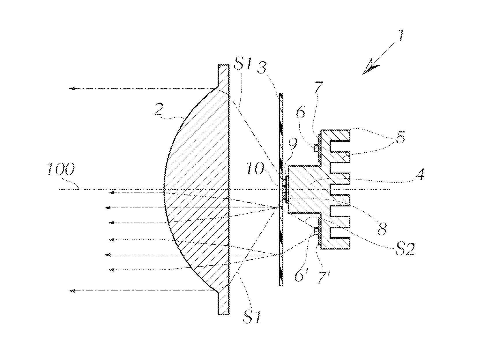
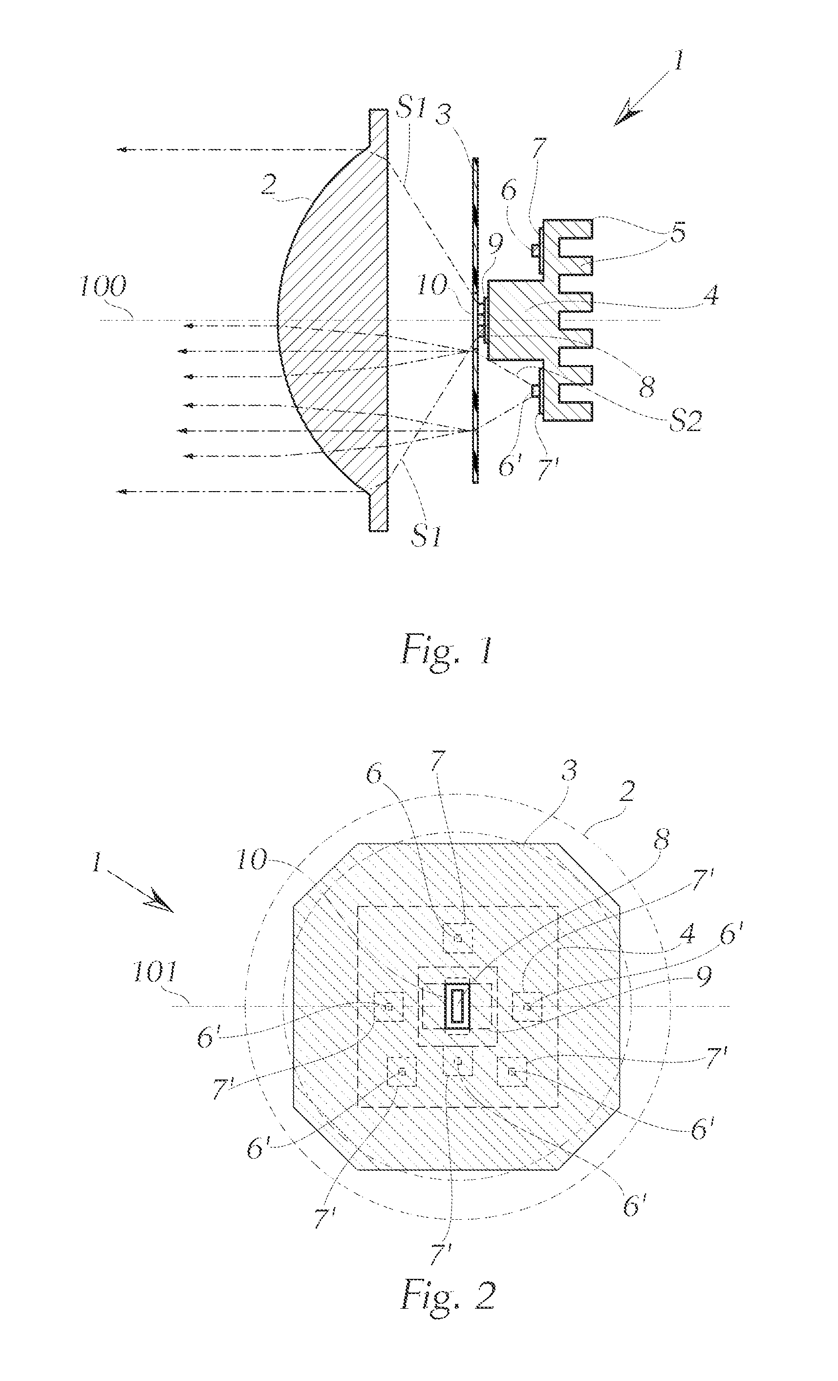
[0023]Just as it is true that the optical axis of the lens does not necessarily have to run through the LED, or through its geometric center in the case of multiple LEDs, the horizontal plane also does not necessarily have to run through the primary LED light source, but instead can be defined by the lens that is displaced vertically, as the result of which the position of the projection (viewing angle) also changes.
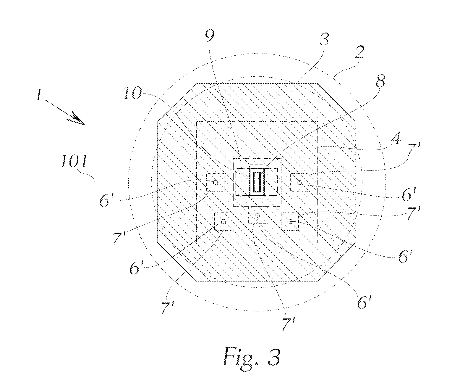
[0024]In principle, the optimum approach would be a larger number of LED light sources for the secondary light source—however, this would be limited by cost and by the available installation space for the headlight. In a simple, cost-effective variant of the invention by which attractive results can be achieved in fully illuminating the lens / diffusion disk, m=0.
[0025]It is furthermore more advantageous in terms of the most uniform possible illumination, if the LED light source(s) above or below the horizontal plane is / are in each case disposed symmetrically in the horizontal direction relative to a vertical plane through the optical axis.

Problems solved by technology

A light module of this type can thus not be incorporated into creating the night design for the vehicle or of the vehicle headlight; i.e., the region of the light module that is outwardly visible appears dark at night whenever the light module has not been activated, and this is often perceived to be unattractive.
Due to the design of the light module that is required to implement the lighting function (high maximum illuminance, e.g., approximately 150 lux) and the correspondingly limited possibility of reducing the LED light output, it is also not possible to operate the lighting function in the dimmed state without exceeding the legally specified values for stray light.
In principle, the optimum approach would be a larger number of LED light sources for the secondary light source—however, this would be limited by cost and by the available installation space for the headlight.
In this way, no passage of secondary light through the aperture of the diffusion disk can occur, which occurrence would cause unwanted effects.
The installation space available for the light module has a limiting effect on these parameters.

Method used


Image

  • LED Light Module
  • LED Light Module
  • LED Light Module

Examples


Embodiment Construction

[0045]The ensuing detailed description provides preferred exemplary embodiments only, and is not intended to limit the scope, applicability, or configuration of the invention. Rather, the ensuing detailed description of the preferred exemplary embodiments will provide those skilled in the art with an enabling description for implementing the preferred exemplary embodiments of the invention. It being understood that various changes may be made in the function and arrangement of elements without departing from the spirit and scope of the invention, as set forth in the appended claims.

[0046]To aid in describing the invention, directional terms are used in the specification and claims to describe portions of the present invention (e.g., upper, lower, left, right, etc.). These directional definitions are merely intended to assist in describing and claiming the invention and are not intended to limit the invention in any way. In addition, reference numerals that are introduced in the spec...


PUM


Abstract

The invention relates to an LED light module for a motor vehicle, or for a headlight for a motor vehicle, wherein the light module comprises a lens and an LED light source, wherein according to the invention a diffusion disk is disposed between the LED light source and the lens as viewed in the light exit direction, wherein the diffusion disk has at least one aperture for the direct passage of at least one component of the light emitted by the LED light source, and wherein the direct component of the light emitted by the LED light source, which component emerges through the aperture of the diffusion disk, is projected through the lens so as to generate a lighting function in the region in front of the motor vehicle.

Description

BACKGROUND OF THE INVENTION[0001]The invention relates to an LED light module for a motor vehicle or for a headlight for a motor vehicle, wherein the light module comprises a lens and an LED light source.[0002]An LED light source of this type can be constructed out of multiple light-emitting diodes (LEDs) that are arranged so as to create “one” common light bundle.[0003]A light module such as that mentioned above is essentially composed of one (or more) LED light source(s), e.g., in the form of a high-power light-emitting diode and a lens, can be used to generate a distribution of light that contains light components over the HD line in the generated light pattern. The lighting function thus implemented (example: high beam, object illumination, . . . ) can only be activated in special driving situations, specifically whenever an object to be illuminated is present in front of the vehicle, or the situation allows the high beam to be turned on.[0004]As a result, a light module of this...

Claims


Application Information

Patent Timeline
Patent Type & Authority Applications(United States)
IPC IPC(8): F21V5/00G01J3/10
CPCF21S48/1154F21S48/1747F21S48/1225F21S41/143F21S41/153F21S41/285F21S41/663
Inventor LUGER, ANDREASMOSER, ANDREAS
Owner ZKW GRP GMBH
Learn More