
Gas injectors for CVD systems with the same

a technology of injectors and cvds, applied in the direction of pipe heating/cooling, crystal growth process, transportation and packaging, etc., can solve the problems of unwanted deposition on surfaces other than the growth substrate, increased particulate levels in the reactor sufficient to decrease the quality of wafers, and coating of chamber walls sufficient to interfere with efficient radiant heating, etc., to improve precursor thermalization and mixing

Inactive Publication Date: 2011-11-17
S O I TEC SILICON ON INSULATOR THECHNOLOGIES
View PDF4 Cites 23 Cited by
  • Summary
  • Abstract
  • Description
  • Claims
  • Application Information

AI Technical Summary

Benefits of technology

To overcome the limitations of the prior art the present invention provides a number of elements, including thermalizing gas injectors, for improving precursor thermalization and mixing, features previously noted to be advantageous.
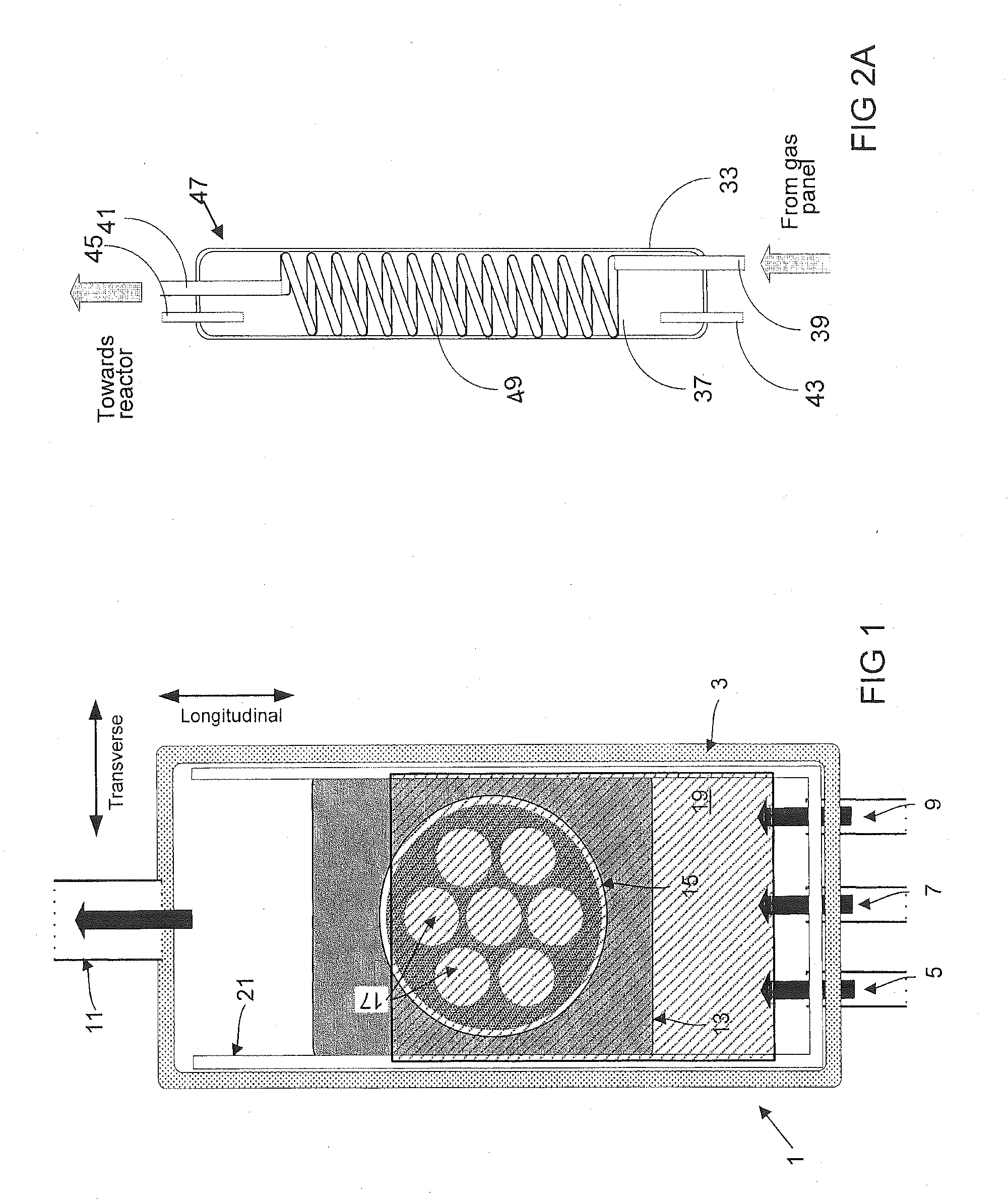
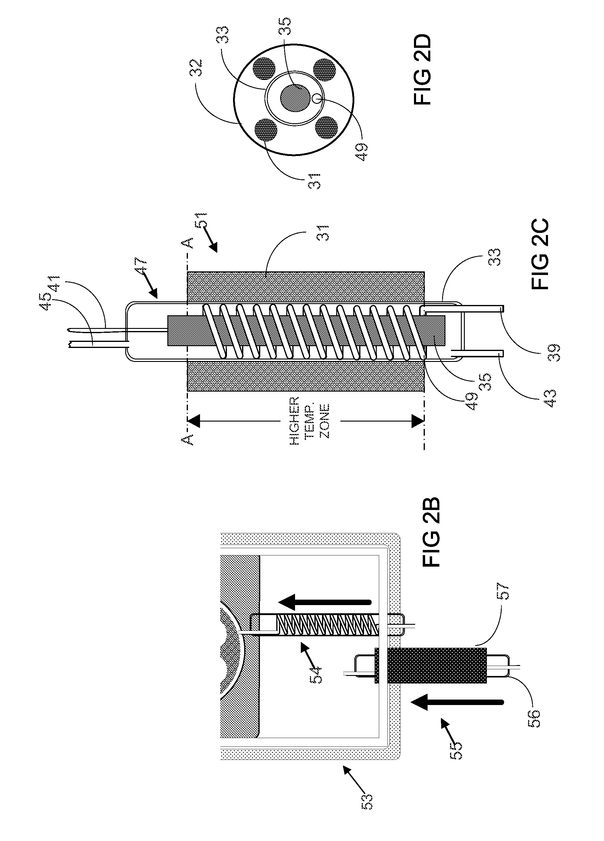
In preferred embodiments, the provided injectors have gas-conducting conduits that include at least one segment configured to have a longer gas flow path, so that gas flow times are increased without decreases in gas flow velocities. The longer segments can be configured to have a spiral-like shape that lengthens the gas flow path between entry and exit. The conduits can also include an outer housing which encloses part of all or the spiral-shaped segment; the outer housing can be provided with external clamp-shell heaters arranged adjacent to the outer housing, or with interior black body elements external to the spiral-shaped segment that enhance heat transfer from the exterior to the gas-conducting conduit; the outer housing can also have a gas inlet port and a gas outlet port that can be configured and sized so that gases can flow through the inner housing from the inlet port to the and outlet port.
Such a system can also include one or more third injectors of the embodiments having a segment configured with a larger cross-sectional size; this injector can be configured and sized so that the larger segment can be arranged interior to a CVD chamber wherein it can be heated by the CVD chamber (when heated); the larger interior segment can be arranged along a longitudinal interior wall of the chamber; this larger segment can have a plurality of outlet ports positioned and oriented to direct multiple gas flows from the lateral wall towards the center of the chamber. Such a system can also include one or more black body plates for enhancing heat transfer from heating elements external to the CVD chamber to the third injectors.
Another embodiment of the invention relates to a method for injecting gases into a CVD (chemical vapour deposition) chamber by conveying gases along a segmented flow path from a gas inlet port to one or more gas outlet ports, with each segment configured or sized to increase gas flow time in comparison to the segments that are not so configured and sized; and heating the one or more segments as the gases are conveyed therethrough. The at least one selected segment provides a gas flow path with a larger cross-section size and increased gas flow times at smaller gas flow velocities with the gases flowing therein including a nitrogen precursor for growth of a Group III-nitride semiconductor in the chamber. Also, at least one other segment has a cross-sectional size that grows larger from an apex section towards a base section where the segment opens into the chamber, with the gases flowing therein including a Group III-metal precursor for growth of a Group III-nitride semiconductor in the chamber. The chamber preferably includes therein a susceptor having a growth surface and the gases of Group III-metal and nitrogen precursors are heated and directed toward the susceptor growth surface for growth of a Group III-nitride semiconductor thereon. Advantageously, the gases react at a temperature approximately greater than 930° C. to facilitate growth of Group III-nitride semiconductor on the susceptor growth surface while minimizing formation of undesirable precursor complexes.

Problems solved by technology

Inadequate thermalization (heating) of precursor gases prior to their injection into a CVD chamber and their premature mixing within the chamber can lead to a number of problems that can be specific to each particular CVD process being performed.
First, injection of inadequately thermalized precursors can lead to unwanted deposition on surfaces other than the growth substrate.
Over time this unwanted material can lead to increased particulate levels in the reactor sufficient to decrease wafer quality, and also to coating of chamber walls sufficient to interfere with efficient radiant heating.
Such undesirable deposition occurs since GaCl3 condenses from the vapour phase at relatively low temperatures, e.g., less than 500° C., and therefore areas of the reactor which are not maintained above vaporization temperatures are likely to become coated.
Further in connection with HVPE processes, injection of inadequately thermalized precursors can lead to unwanted side reactions that limit actual GaN deposition.
Premature mixing of the precursor gases can result in unwanted reaction by-products and the production of particulates within the reactor.
However, thermalization of the group V ammonia precursor should not be carried out in an environment containing metals, e.g., in metallic gas lines, metallic reactor components, etc., as is often done.
The above problems resulting from inadequate thermalization and premature mixing result in an inefficient reaction of the precursor gases to form the GaN product at the substrate.
Precursor reactants are lost due to particle / complex formation, deposition on unwanted surfaces, and so forth.
However, this prior art is concerned with conventional equipment where GaCl is formed in situ by reacting HCl gas with liquid gallium and is not applicable to equipment that directly injects gaseous GaCl3.

Method used


Image

  • Gas injectors for CVD systems with the same
  • Gas injectors for CVD systems with the same
  • Gas injectors for CVD systems with the same

Examples


Embodiment Construction

The present invention provides improved gas handling for chemical vapour deposition (CVD) reactors systems, especially CVD systems used for semiconductor processing and more especially CVD systems having chambers with generally rectangular cross-sections in which a planar flow of precursor gases crosses a substrate at which deposition or other reactions take place. Exemplary CVD chambers in which the invention can be usefully applied are briefly described before turning to the invention.

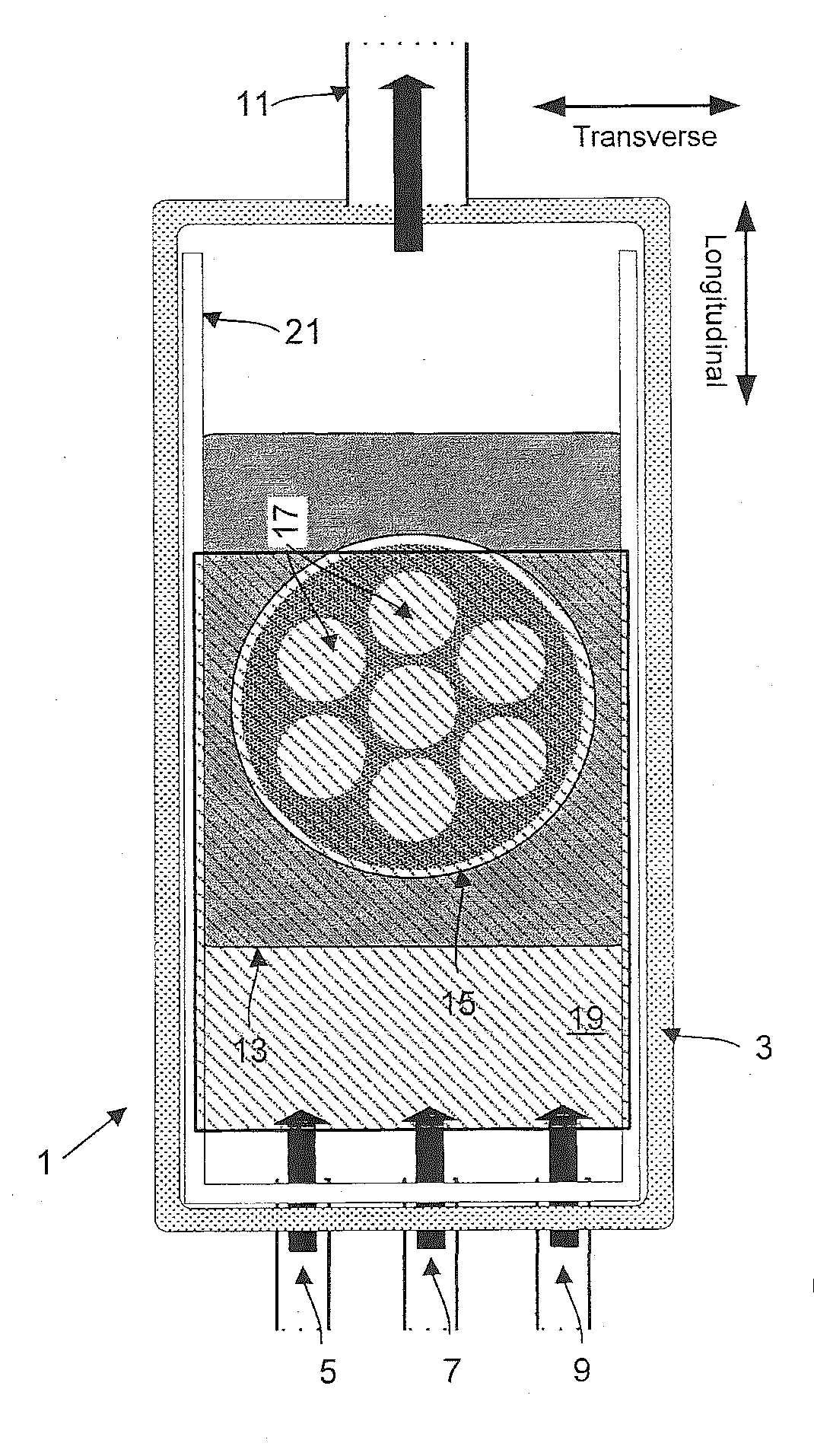
FIG. 1 illustrates in plan view relevant detail of exemplary CVD chamber 1 to which this invention is applicable. FIG. 3A illustrates in cross-section view a similar CVD reactor. Common reference numbers identify similar elements in both figures. Exemplary reactor 1 includes reactor chamber 3 which is usually made of quartz so that it can be heated by external, radiant heating lamps. Process gases including precursor gases and purge gases enter chamber 3 at the bottom of the figure through ports (or ...


PUM

PropertyMeasurementUnit
temperatureaaaaaaaaaa
temperaturesaaaaaaaaaa

Abstract

The present invention provides improved gas injectors for use with chemical vapour deposition (CVD) systems that thermalize gases prior to injection into a CVD chamber. The provided injectors are configured to increase gas flow times through heated zones and include gas-conducting conduits that lengthen gas residency times in the heated zones. The provided injectors also have outlet ports sized, shaped, and arranged to inject gases in selected flow patterns. The invention also provides CVD systems using the provided thermalizing gas injectors. The present invention has particular application to high volume manufacturing of GaN substrates.

Description

FIELD OF THE INVENTIONThe present invention relates to semiconductor processing equipment, and in particular, provides gas injectors that inject thermalized gases into CVD chambers, and injectors that inject thermalized gases in pre-determined flow patterns. The present invention also provides CVD systems using the provided gas injectors. The invention has particular application to high volume manufacturing of GaN substrates.BACKGROUND OF THE INVENTIONInadequate thermalization (heating) of precursor gases prior to their injection into a CVD chamber and their premature mixing within the chamber can lead to a number of problems that can be specific to each particular CVD process being performed. Consider, as an example, the hydride-vapour-phase epitaxial (HVPE) growth of GaN using GaCl3, and NH3 as the precursor gases, where problems caused by inadequate thermalization and premature mixing include the following.First, injection of inadequately thermalized precursors can lead to unwant...

Claims


Application Information

Patent Timeline
Patent Type & Authority Applications(United States)
IPC IPC(8): C30B23/06F16K49/00C23C16/34
CPCC23C16/34C23C16/45548C30B29/403C23C16/45574C30B25/14C23C16/4557Y10T137/6416H01L21/0262
Inventor ARENA, CHANTALBERTRAM, JR., RONALD THOMASLINDOW, ED
Owner S O I TEC SILICON ON INSULATOR THECHNOLOGIES
Learn More