
Manufacturing method of electronic part

a manufacturing method and electronic technology, applied in the direction of resistor details, pretreatment surfaces, coatings, etc., can solve the problems of combustible apparatus, deformation of outer cover film, and degradation of heating-flow rate (flowability) of resin itself, and achieve excellent explosion resistance, excellent flame retardant properties, and high rubber elasticity

Inactive Publication Date: 2011-11-10
NIPPON CHIMI CON CORP
View PDF6 Cites 14 Cited by
  • Summary
  • Abstract
  • Description
  • Claims
  • Application Information

AI Technical Summary

Benefits of technology

[0023]According to the present invention, the following effects are acquired.
[0024](1) The first outer cover film that contacts an electronic part device and that has a secured incombustibility and the second outer cover film that has high rubber elasticity, excellent explosion proof, and excellent flame retardant property are formed and, therefore, even when the electronic part is broken due to application of an overvoltage, combustion of the outer cover material can be securely prevented and external scattering of ceramic contents and the outer cover material itself can be prevented. Therefore, even when the electronic part is broken, spread of the fire to the surrounding apparatuses, etc., can be prevented.
[0025](2) The first outer cover film main material is substantially evenly dispersed and, thereby, incombustibility of the first outer cover film is improved.
[0026](3) In the case where air in cavity portions of the first outer cover film is removed, when the second outer cover film is formed, the second outer cover film can be formed whose thickness is substantially even, that has no pinhole and no air bubble involved therein, that has an excellent flame retardant property, that has improved explosion proof, and whose withstand voltage is excellent.

Problems solved by technology

With the increased uses of plastic and the dense mounting of the electronic parts, a burnout of its electronic part may cause the apparatus to combust.
However, the heating-flow rate (flowability) of the resin itself is degraded and it becomes difficult to form the outer cover film.
However, it is known as to powder resin coating that it becomes difficult to form the outer cover film when the amount of the resin is equal to or less than 30 [wt %].
However, the bromine constituent gasified imposes a heavy load on the environment such as destruction of the ozone layer and, therefore, use of the agent tends to be restricted.
A silicone paint has a flame retardant property but is not incombustible and, therefore, the silicone paint has a weak function of suppressing combustion.
Silicone rubber may combust at a high temperature that causes a penetrating portion in the device.

Method used


Image

  • Manufacturing method of electronic part
  • Manufacturing method of electronic part
  • Manufacturing method of electronic part

Examples


first example

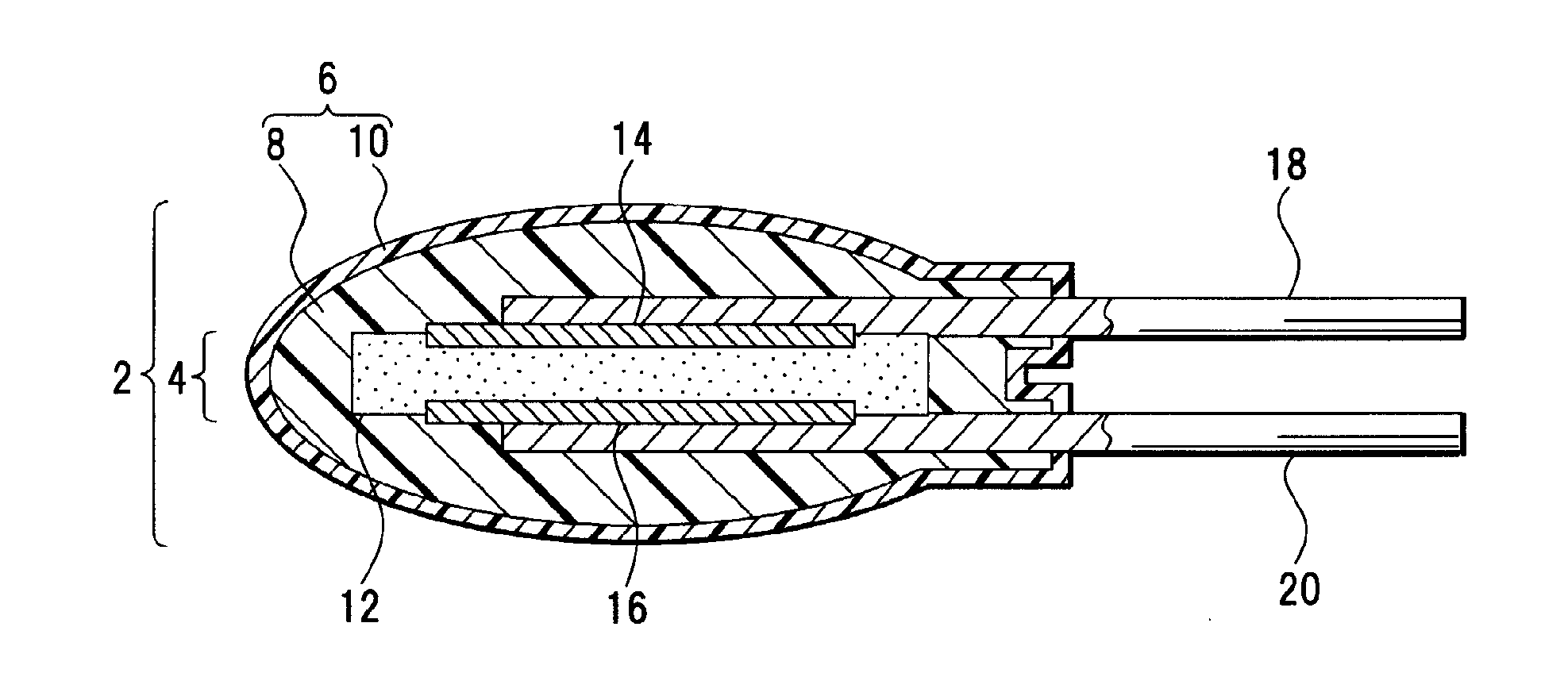
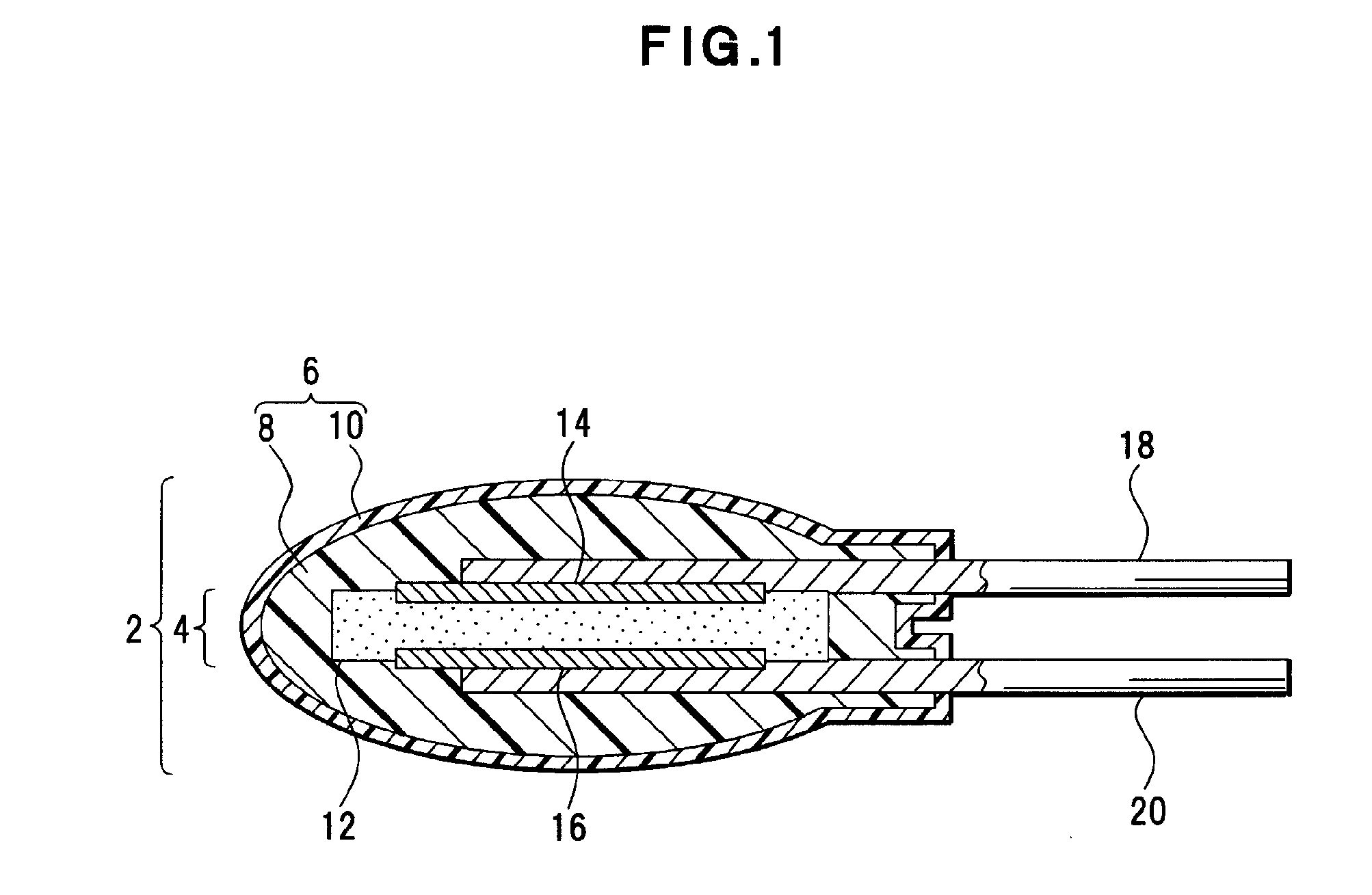
[0065]A first example of the varistor of the present invention will be described. To configure the varistor 2 that has a structure depicted in FIG. 1, a ceramic device assembly is used as the varistor device assembly 12 of the device 4. For the varistor device assembly 12 formed by the ceramic device assembly, for example, a varistor device assembly is used: that is formed by printing and sintering the electrodes 14 and 16 each having the diameter of 8 [mm] on both sides of a sintered object that has the diameter of 10 [mm] and that includes zinc oxide as its main constituent added with magnesium oxide, bismuth oxide, cobalt oxide, etc.; and that has the lead terminals 18 and 20 soldered on the surface of each of the electrodes 14 and 16.

[0066]The organic solvent is mixed into the liquid-form first outer cover film main material that is for configuring the outer cover film 8 and, thereby, the outer cover film liquid material 30 is acquired. The varistor device assembly 12 having the...

second example

[0076]In the first example, the case where aluminum hydroxide is added to the silicone elastomer has been described. However, in a second example, the same result was also acquired when the silicone resin was used instead of the silicone elastomer and when magnesium hydrate or calcium hydrate was used instead of aluminum hydroxide. Aluminum hydroxide is mainly used as the flame retardant agent, and magnesium hydrate and calcium hydrate each present the flame retardant property based on the same mechanism as that of aluminum hydroxide.

third example

[0077]In the first example, the outer cover film 10 is formed in the ordinary-pressure ambient atmosphere. However, in a third example, the outer cover film 8: is immersed in the outer cover film liquid material 34 in reduced-pressure ambient atmosphere whose pressure is 2 [kPa]; and is lifted up from the outer cover film liquid material 34 in the ordinary-pressure ambient atmosphere, and, thereby, the outer cover film 10 is formed. The ordinary-pressure ambient atmosphere is an example of the state where the condition of the reduced-pressure ambient atmosphere is cancelled, and the state of the ambient atmosphere is not limit to this.

[0078]The device 4 having the lead terminals 18 and 20 soldered thereto: is dipped in the outer cover film liquid material 30 having the organic solvent mixed thereinto; is lifted up therefrom; and, thereafter, is hardened by heating the device 4 at 100 [° C.] for 30 [min]. Thereby, the outer cover film liquid material 30 is coated and fixed on the cir...


PUM


Abstract

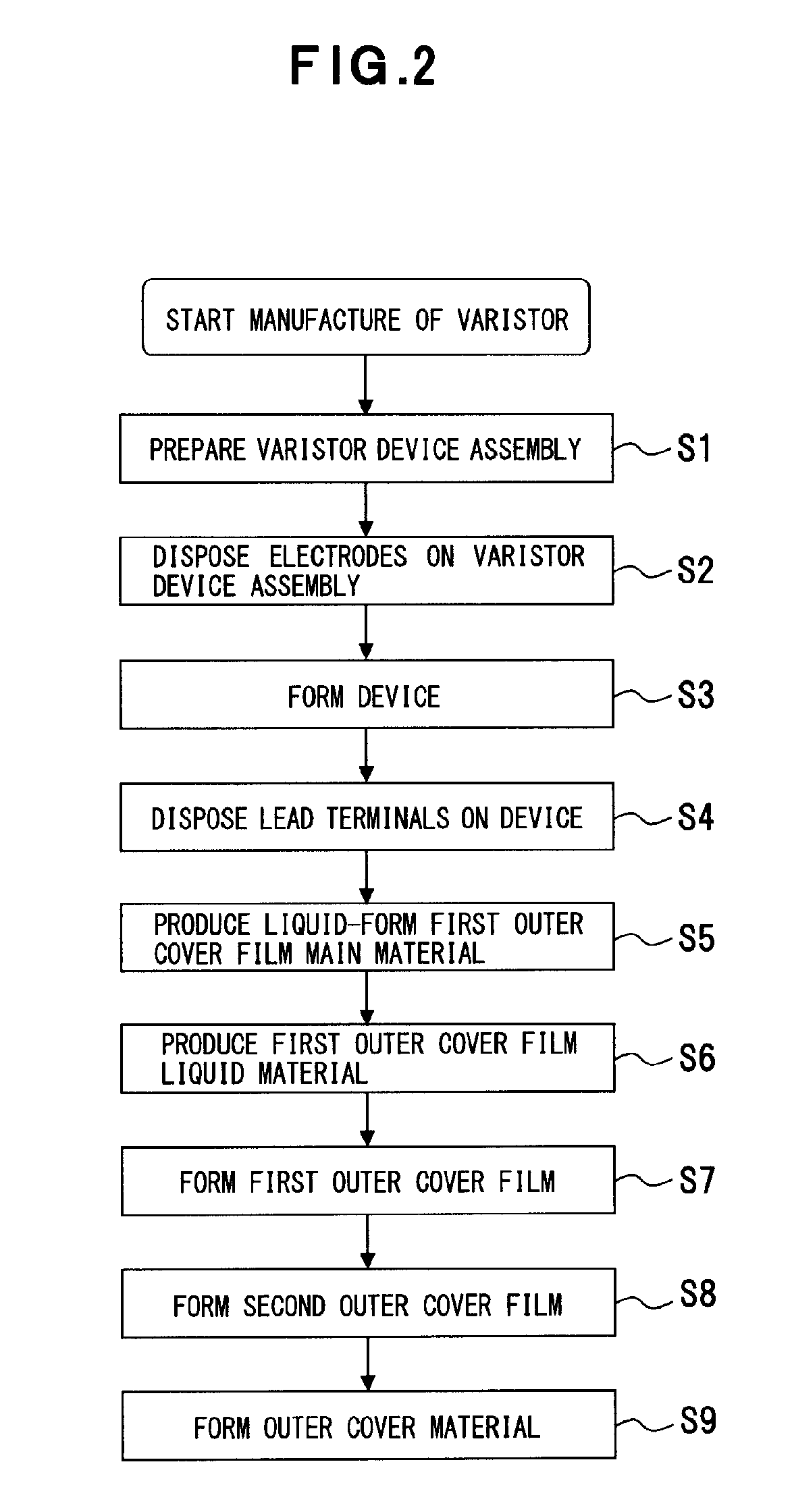
A manufacturing method of an electronic part (varistor 2) whose device 4 is covered by an outer cover material 6, including the steps of: forming a first outer cover film 8 by coating and fixing a first outer cover film liquid material 30 that includes an organic solvent, on the device 4; and forming a second outer cover film 10 by coating and fixing a second outer cover film liquid material 34, on the first outer cover film 8. The first outer cover film includes a silicone resin or a silicone elastomer, and one or more kind (s) of aluminum hydroxide, magnesium hydrate, or calcium hydrate at a weight ratio ranging from 45 / 55 to 5 / 95.

Description

TECHNICAL FIELD[0001]The present invention relates to a manufacturing method of an electronic part whose device is covered by an outer cover material and, for example, relates to a manufacturing method of an electronic part such as a voltage-dependent non-linear resistor (varistor) that is made incombustible using an incombustible material for its outer cover material.BACKGROUND ART[0002]In each of various apparatuses such as an electronic apparatus or an electric apparatus, plastic is used not only for its housing but also for many of its portions and parts to reduce the weight of the apparatus and, in addition, electric parts are densely mounted to cope with the demand for downsizing of the apparatuses. With the increased uses of plastic and the dense mounting of the electronic parts, a burnout of its electronic part may cause the apparatus to combust.[0003]A varistor is present as an electronic part that is mounted on such an apparatus. The varistor has a voltage-dependent non-li...

Claims


Application Information

Patent Timeline
IPC IPC(8): B05D5/00B05D3/02B05D1/36
CPCH01C1/028H01C7/102H01C1/148H01C1/032H01C17/02H01C7/10
Inventor SAEGUSA, KAZUHIROSATOU, SINYAAIZAWA, SHOGO
Owner NIPPON CHIMI CON CORP
Learn More