
Method For Geophysical Imaging

Active Publication Date: 2011-10-27
EXXONMOBIL UPSTREAM RES CO
View PDF10 Cites 26 Cited by
  • Summary
  • Abstract
  • Description
  • Claims
  • Application Information

AI Technical Summary

Benefits of technology

[0024]In some of its embodiments, the present invention uses regularization functions, F, based upon low-frequency seismic information and the diffusion equation, to invert electromagnetic geophysical data for resistivity models that match seismically-derived structural models. The seismic earth model is preferably derived at a resolution that is consistent with the resolution of the electromagnetic data which consist of multiple temporal frequencies. The seismic earth model will further suggest appropriate symmetry axes for the resistivity anisotropy and will indicate regions (such as salt or other extrusion features) where the resistivity may be isotropic. Seismic consistency is implemented as an objective of the inversion (instead of as a hard constraint) to allow for uncertainties and errors in the seismic earth model. With this information implemented in the objective function, structural consistency can be maintained during the inversion and anisotropic resistivities can be separated from the effects of geological structure and inhomogeneity, thus providing more reliable subsurface resistivities.

Problems solved by technology

Even with these different types of regularization, the resistivity images from CSEM data inversions generally still lack structural consistency with subsurface structure derived from other sources, such as seismic data.
This structure inconsistency makes geological interpretation difficult and the prediction of hydrocarbon presence less reliable.
Since the subsurface rock properties are both anisotropic and inhomogeneous over the distances probed by geophysical data, it is often difficult to unravel intrinsic from structurally-induced anisotropy.
Such straightforward electrical inversion can fail to predict the orientations of the symmetry axes (even on synthetic data from a simple model) when the orientations vary in space (Pain, et al, 2003).
It is difficult to derive reliable orientations of symmetry axes and principle resistivities from the measured CSEM data in geological settings encountered in hydrocarbon exploration, and it is even more difficult to correlate the derived orientations to that from other sources, such as seismic data.
In any event, the problems of inverting CSEM data to a resistivity model that is consistent with the subsurface structure derived from other sources, such as seismic data, can not be achieved by those common regularizations without utilizing the a priori structure information.
Due to the complexity of the subsurface rock, it is very challenging to build rock physics relationships that work for the wide variety of rock mixtures.
Moreover, different geophysical data types respond to changes in subsurface properties over very different length scales, making it ambiguous how the properties should be averaged into the rock-property relationships.
These errors and complexities make the practical application of this direct method of joint inversion difficult.
The inversion usually breaks this consistency due to the discrepancy between the starting model and the actual subsurface resistivity, limited data coverage, resolution, and non-uniqueness.
This method is both labor-intensive and computationally inefficient.
It becomes impractical or can fail to converge to the correct answer when more than two types of data are included.
In practical application, it is very difficult for the two images to converge to the same structure due to factors such as the limited data coverage, rapid decay of the electric fields, subsurface anisotropy, unknown orientations of symmetry axes, and errors in the initial electrical and seismic models.
These factors can lead to model gradients that are very poorly behaved (poorly correlated with the seismic data) during the iterations.
Also, the subsurface anisotropy, which is important for the inversion of electromagnetic data, is not addressed by this cross-gradient method.
These authors, moreover, specifically add a regularization term to penalize the intrinsic anisotropy of the unknown material, apparently on the theory that allowing the intrinsic resistivities to vary freely can result in erroneous solutions and that the most realistic solutions are those with the smallest anisotropy.
Since the subsurface rock properties are both anisotropic and inhomogeneous over the distances probed by geophysical data, it is often difficult to unravel intrinsic anisotropy (a property of the rocks) from structurally-induced anisotropy (an aggregate property of rocks).
Simply forcing both the resistivities and orientations of the electrical symmetry axes to follow the same a priori structure during CSEM inversion may not generate geologically-consistent and reliable orientations of the electrical symmetry axes.
The error in symmetry axis orientations will translate to error in the resistivity images, which can impact the interpretation of the subsurface.
The non-uniqueness problem exists in most geophysical data inversions, and is especially true for CSEM data due to the low resolution and exponential decay of the fields.
All these factors combined with the complex geological settings encountered in hydrocarbon exploration make the prediction of the full anisotropic resistivities, especially the orientations of the symmetry axes, difficult using CSEM data alone.

Method used


Image

  • Method For Geophysical Imaging
  • Method For Geophysical Imaging
  • Method For Geophysical Imaging

Examples


Embodiment Construction

Inversion with Structure Constraint

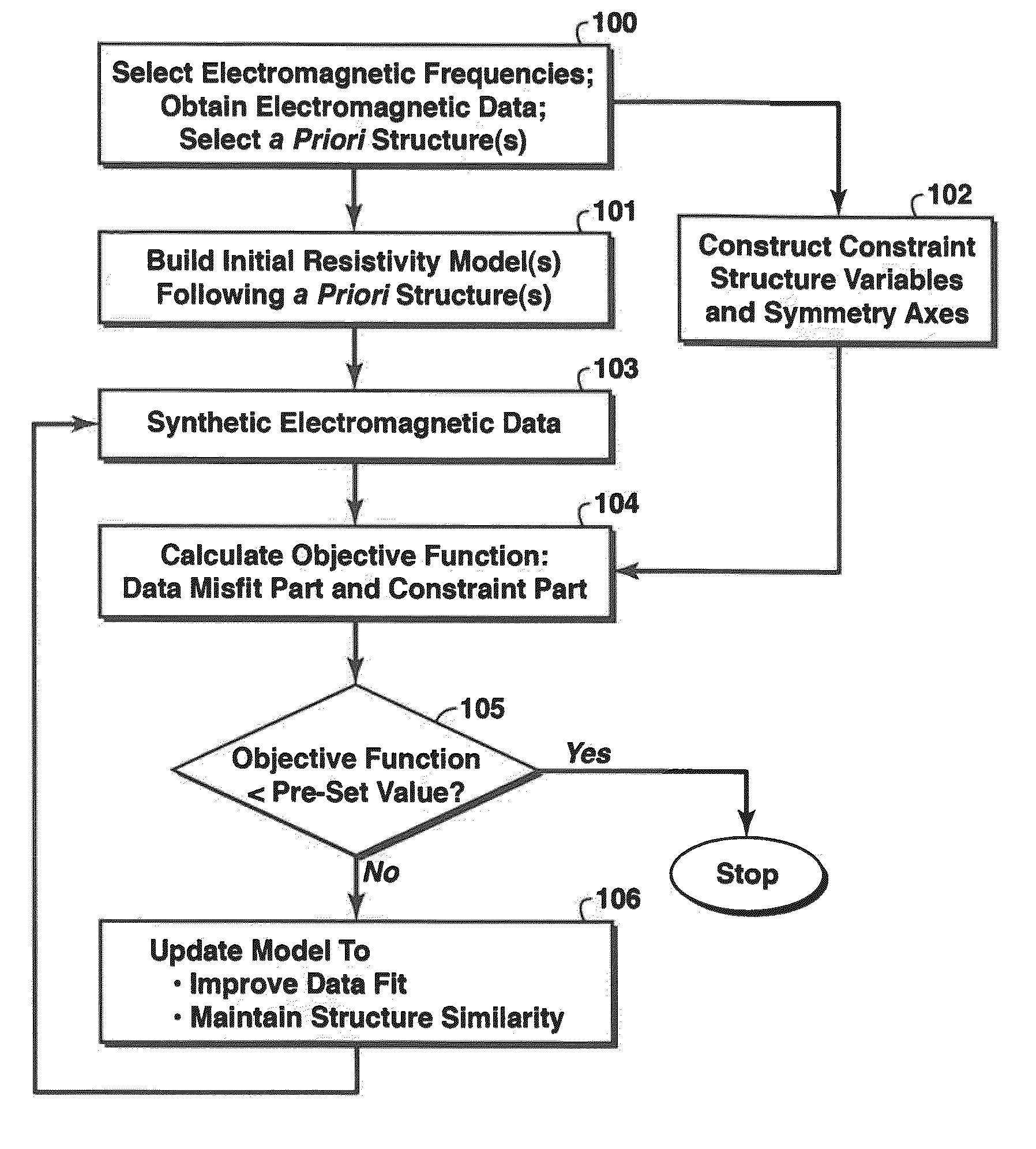
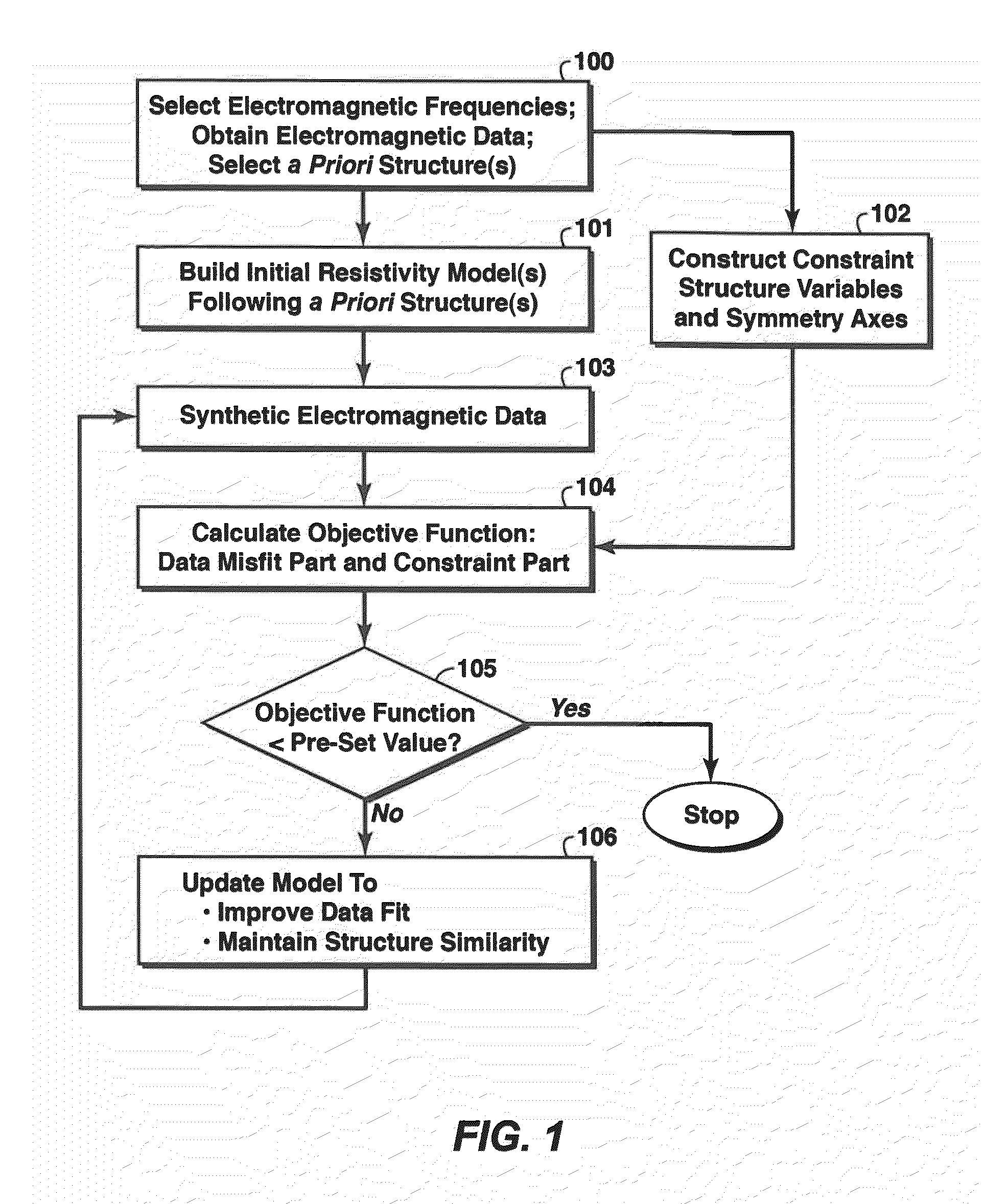
[0040]Basic steps in one embodiment of the present invention are shown in the flow chart of FIG. 1. In this embodiment, the a priori structure information is injected as regularization in the objective function of the inversion to encourage the resistivity model to follow the a priori structure and honor any other a priori geological and geophysical constraints.

[0041]In step 100, electromagnetic data are obtained. A minimum of two frequencies and preferably six frequencies will be chosen to span the range from 0.1 Hz to 2.0 Hz More generally, frequencies may be chosen to span the range 0.005 Hz to 10 Hz following the methods of U.S. Pat. No. 7,539,279, “Logarithmic Spectrum Transmitter Waveform for Controlled-Source Electromagnetic Surveying,” to Lu and Srnka; or Hornbostel and Green, “CSEM survey design for successful imaging,” Expanded Abstracts of the 27th Annual International Meeting, Society of Exploration Geophysicists, pp. 682-686 (2008). In...


PUM


Abstract

Method for transforming electromagnetic survey data acquired from a subsurface region to a subsurface resistivity model indicative of hydrocarbon accumulations or lack thereof. In one embodiment, data are selected for two or more non-zero frequencies (100), and a structural model of the region is developed based on available geological or geophysical information. An initial resistivity model of the region is developed based on the structural model (101), and the selected data are inverted to update the resistivity model (106) by iterative forward modeling (103) and minimizing an objective function (105) including a term measuring mismatch between model synthesized data and measured survey data, and another term being a diffusive regularization term that smoothes the resistivity model (104). The regularization term can involve a structure or geology constraint, such as an anisotropic resistivity symmetry axis or a structure axis, determined from the a priori information (102).

Description

CROSS-REFERENCE TO RELATED APPLICATION[0001]This application claims the benefit of U.S. provisional patent application 61 / 326,456 filed Apr. 21, 2010 entitled METHOD FOR GEOPHYSICAL IMAGING, the entirety of which is incorporated by reference herein.FIELD OF THE INVENTION[0002]This invention relates generally to the field of geophysical prospecting and, more particularly, to inversion of electromagnetic survey data to obtain a resistivity model of the subsurface. Specifically, the invention is a method for inverting electromagnetic geophysical data to produce a subsurface resistivity model that is consistent with at least one other subsurface image or model derived from other geological or geophysical information, such as geology structure interpretation, seismic velocity fields, and seismic images. Such resistivity images are generally useful for predicting rock properties and for inferring the presence or absence of hydrocarbons in the subsurface.BACKGROUND OF THE INVENTION[0003]Th...

Claims


Application Information

Patent Timeline
IPC IPC(8): G06F17/10G06G7/48
CPCG01V3/38
Inventor JING, CHARLIEWILLEN, DENNIS E.
Owner EXXONMOBIL UPSTREAM RES CO
Learn More