Membrane loop process for separating carbon dioxide for use in gaseous form from flue gas

a technology of carbon dioxide and gaseous form, which is applied in the field of membrane-based gas separation process, can solve the problems of power plants producing enormous amounts of flue gas, and achieve the effects of enhancing oil recovery, reducing the potential contribution of global warming, and enhancing the recovery of coalbed methan

Active Publication Date: 2011-10-27
MEMBRANE TECH & RES
View PDF10 Cites 29 Cited by
  • Summary
  • Abstract
  • Description
  • Claims
  • Application Information

AI Technical Summary

Benefits of technology

[0015]The process of the invention further involves building up the concentration of carbon dioxide in a gas flow loop between the combustion step and the membrane separation step. A portion of the carbon dioxide-enriched gas can then be withdrawn from this loop and transported, without the need to liquefy the gas or otherwise create a high-purity stream, to a destination where it is used or confined, preferably in an environmentally benign manner. One preferred option is to direct the gas to an operation or facility that converts the carbon dioxide to oxygen by photosynthesis, such as an algae farm. A second preferred option is to use the gas for enhanced oil recovery. A third preferred option is to use the gas to enhance the recovery of coalbed methane. A fourth preferred option is to use the gas to precipitate calcium and magnesium in sea water, to immobilize the carbon dioxide and potentially produce cement and aggregate. A fifth preferred option is to inject the gas into a sub-surface aquifer or salt brine layers to sequester the carbon dioxide, thereby reducing its potential contribution to global warming.
[0023]The residue stream from the membrane separation step forms the treated exhaust gas, preferably containing less than about 5 vol % carbon dioxide, as mentioned above. This stream is typically, although not necessarily, discharged to the environment. The substantial reduction of the carbon dioxide content in the raw exhaust greatly reduces the environmental impact of discharging the stream.
[0027]The process is thus distinguished from processes that require the carbon dioxide to be further concentrated to a purity of 95 vol % or above. Such processes usually involve either liquefaction of the carbon dioxide by low-temperature distillation, or absorption of the carbon dioxide into a chemical or physical sorbent, followed by regeneration of the sorbent to yield a high-purity carbon dioxide product. The process of the invention does not require these steps, so is often much lower in energy consumption than such processes.
[0032]According to a preferred process of the invention, a gas stream is produced that contains approximately 30 to 50 vol % carbon dioxide at very low cost. This gas stream can then be used on-site or may be transported to a location where it can be put to effective use. If the gas needs to be transported, transportation of the concentrated gas is far more economical than transporting conventional, untreated flue gas. Typically, the volume of gas that must be pipelined is reduced five-fold or more.

Problems solved by technology

In particular, power plants generate enormous amounts of flue gas.

Method used


Image

  • Membrane loop process for separating carbon dioxide for use in gaseous form from flue gas
  • Membrane loop process for separating carbon dioxide for use in gaseous form from flue gas
  • Membrane loop process for separating carbon dioxide for use in gaseous form from flue gas

Examples


example 1

Bases of Calculations for Other Examples

[0111](a) Membrane permeation experiments: The following calculations were performed using a composite membrane having a polyether-based selective layer with the properties shown in Table 1.

TABLE 1GasPermeance (gpu)*CO2 / Gas SelectivityCarbon dioxide1,000  —Nitrogen3033Oxygen6017Hydrogen100 10Carbon 11,000Water5,000** —*Gas permeation unit; 1 gpu = 1 × 10⁻⁶ cm3(STP) / cm2 · s · cmHg**Estimated, not measured

[0112](b) Calculation methodology: All calculations were performed using a modeling program, ChemCad 5.6 (ChemStations, Inc., Houston, Tex.), containing code for the membrane operation developed by MTR's engineering group. For the calculations, all compressors and vacuum pumps were assumed to be 75% efficient. In each case, the modeling calculation was performed to achieve 90% recovery of carbon dioxide from the flue gas stream.

[0113](c) “No membrane” example: A computer calculation was performed to determine the chemical composition of untreat...

examples 2-8

Processes of the Invention: Modeling of Sweep-Based Membrane Separation Step and Effect on Combustion Step

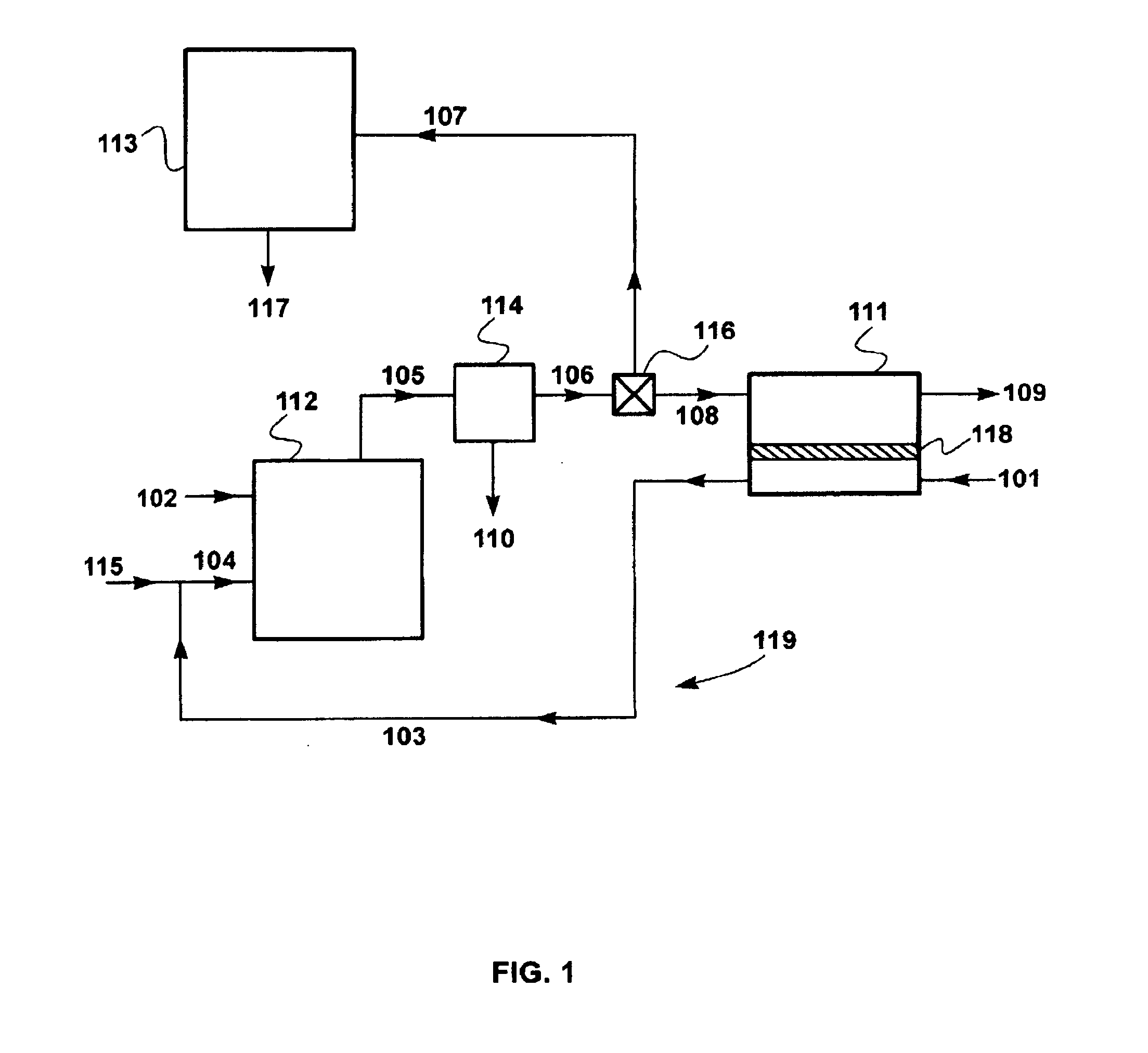
[0117]A set of calculations was performed to model the effect of various process parameters on the performance of the sweep-based membrane separation step and its effect on the combustion step. The calculations for Examples 2 through 8 were performed using the flow scheme shown in FIG. 1 and described in the Detailed Description, above. This flow scheme includes a sweep-based membrane separation step, 111.

[0118]To facilitate operation of the calculation software, the base case air flow provided to the combustor via the membrane permeate side was assumed to be about 740 m3 / h (950 kg / h), compared with the typical air flow to a 500 MW power plant of about 1.8 million m3 / h used for the calculation of Example 1. In other words, the scale of the calculations for Examples 2 through 8 was about 1 / 2,400 of the scale for a typical coal-fired power plant. This reduces membrane area proport...

example 2

Process of the Invention

[0119]In this example, the membrane area was assumed to be 400 m2, and the combustion exhaust stream split ratio was set at 1:1 (bleed flow of partially concentrate product gas:flow to sweep-based membrane separation step). The separation was assumed to be performed using a membrane having permeation properties as in Table 1. The results of this calculation are shown in Table 3.

TABLE 3StreamPartiallyCondenserConcentratedMembraneAirGas toCoalKnockoutProduct GasFeedSweepCombustorRetentate(102)(110)(107)(108)(101)(103)(109)ParameterTotal Flow (kg / h)55465545549501100404Temperature (° C.)25404040253325Pressure (bar)1.01.01.01.01.01.01.0Component (vol %)Coal (carbon +100000000hydrogen)Oxygen001.61.621.017.55.2Nitrogen0071.871.879.070.691.9Carbon Dioxide0019.219.208.32.9Water01007.47.403.60

[0120]Compared with the “no membrane” Example 1, the carbon dioxide content in the combustion exhaust stream (membrane feed), 108, and the partially concentrated product gas, 107,...


PUM


Abstract

The invention is a process involving membrane-based gas separation for separating and recovering carbon dioxide emissions from combustion processes in partially concentrated form, and then transporting the carbon dioxide and using or storing it in a confined manner without concentrating it to high purity. The process of the invention involves building up the concentration of carbon dioxide in a gas flow loop between the combustion step and a membrane separation step. A portion of the carbon dioxide-enriched gas can then be withdrawn from this loop and transported, without the need to liquefy the gas or otherwise create a high-purity stream, to a destination where it is used or confined, preferably in an environmentally benign manner.

Description

FIELD OF THE INVENTION[0001]The invention relates to membrane-based gas separation processes, and specifically to loop processes for recycling carbon dioxide in gaseous form from flue gas, where the recovered carbon dioxide can be transported for use or confinement in partially concentrated form.BACKGROUND OF THE INVENTION[0002]Many combustion processes produce flue gases contaminated with carbon dioxide that contribute to global warming and environmental damage. Such gas streams are dilute, low-pressure, and difficult to treat; therefore, this gas cannot be economically transported to places where the carbon dioxide could be used.[0003]To make transportation more feasible, the carbon dioxide can be separated and enriched to produce 90-100% pure carbon dioxide. While this concentrated carbon dioxide can be easily transported, the separation processes required to concentrate the carbon dioxide remain expensive. As such, there remains a need for better treatment options.[0004]Gas sepa...

Claims


Application Information

Patent Timeline
IPC IPC(8): C01B31/20C01B32/50
CPCB01D53/22Y02C10/08B01D2256/22B01D2257/504F23J15/006F23J15/02F23J2215/50F23J2219/00F23L7/007Y02C10/04Y02C10/10Y02E20/344Y02C20/20B01D2311/13B01D53/62Y02E20/32Y02E20/34Y02C20/40
Inventor WIJMANS, JOHANNES G.BAKER, RICHARD W.MERKEL, TIMOTHY C.
Owner MEMBRANE TECH & RES
Why Eureka
Try Eureka