
Flexible manufacturing system

Active Publication Date: 2011-10-27
XOMA US
View PDF72 Cites 61 Cited by
  • Summary
  • Abstract
  • Description
  • Claims
  • Application Information

AI Technical Summary

Benefits of technology

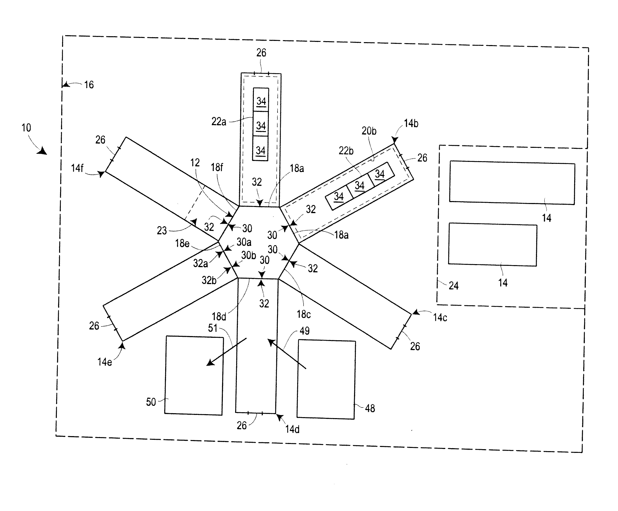
[0004]The invention provides a manufacturing system comprising (a) a core that is adapted to supply utilities for multiple manufacturing processes and preferably is capable of high capacity supply, (b) and at least two, three, four, five, six, seven, eight, nine, ten or more movable manufacturing bays adapted to be removably coupled to the core and adapted for receiving the utilities supplied from the core. In some embodiments, within the workspace defined by each bay, there is a facility for performing one or more manufacturing processes, or portions or steps of manufacturing processes, which can optionally be performed in parallel. The facility may comprise a plurality of components, each of which performs one or more portions or steps of a chemical, a biological, a pharmaceutical, or some other manufacturing process. The manufacturing system optionally includes a plurality of clean connect areas positioned adjacent to the manufacturing bays when connected to the core for controlling access to the manufacturing bays and / or providing a clean area for making the utility connections between the core and the manufacturing bays. The manufacturing system further optionally includes a plurality of upper docking collars positioned above the bays when connected to the core for supplying one or more utilities to the bays (e.g., under the force of gravity). The manufacturing system optionally comprises one, two, or more holding areas where a movable bay can be cleaned, and where optionally the configuration of components that perform the manufacturing process, or portions or steps of manufacturing processes, can be reconfigured. The manufacturing system optionally comprises a drain, adapted to be removably connected to the one or more movable manufacturing bays, for discharging waste generated during a manufacturing process. The drain for discharging waste is preferably isolated from the core, so as to avoid contamination of the core.
[0005]The invention also provides methods of manufacturing products that utilize one or more of the components of such a manufacturing system. The systems and methods of the invention provide a number of benefits, including flexibility and the ability to reduce the time and cost of reconfiguring manufacturing from one technology and / or product to a different technology and / or product (e.g., bacterial host cells, yeast / fungal host cells, insect host cells, mammalian host cells producing protein, mammalian host cells producing virus, plant cells or algae), and / or upgrading to newer, more efficient technology, and / or changing production capacity (increasing or decreasing production) or batch size (e.g., 100 L to 2750 L, 5,000L to 20,000 L or vice versa), and / or decreasing the changeover time from a first batch production run to a second batch production run, which may be of the same or a different type of production run as the first production run, and / or changing from manufacturing suitable for pre-clinical purposes (GLP, or Good Laboratory Practice) to manufacturing suitable for FDA or other government regulatory agency approved therapeutics (GMP, or Good Manufacturing Practice), or vice versa.
[0007]The manufacturing system and methods of the invention offer the added advantage of providing secure and controlled employee access to multiple distinct and potentially proprietary technologies. In a single manufacturing system, each manufacturing bay can have a separate access and separate security system, such that different companies could own or otherwise arrange for use of (e.g., lease) different bays and permit only their authorized employees to access the company's proprietary technologies. In some embodiments, the core and at least one manufacturing bay have different personnel with no cross contact.

Problems solved by technology

Some manufacturing facilities may house multiple manufacturing suites to allow parallel manufacturing campaigns, but limitations remain in this configuration, such as for example, the time required to convert or modify a particular manufacturing suite for use in manufacturing a different product (e.g., different technologies or types of products), as well as to complete a changeover process (e.g., cleaning) between manufacturing campaigns of similar or different products.
In addition, the potential for cross-contamination between different types of technology or products may limit the ability to house parallel production systems within the same facility.

Method used


Image

  • Flexible manufacturing system
  • Flexible manufacturing system
  • Flexible manufacturing system

Examples


Embodiment Construction

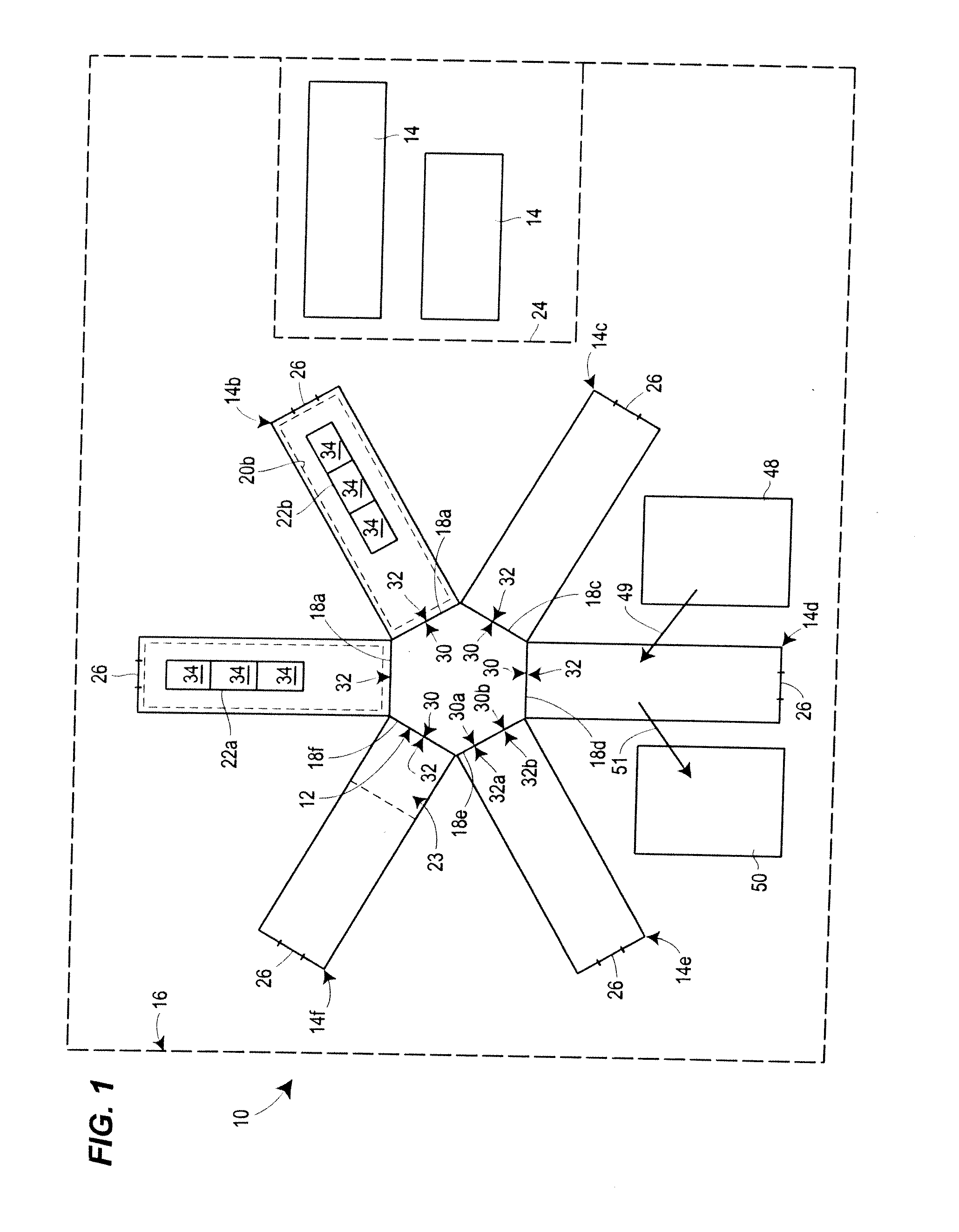
view of one embodiment of a manufacturing system of the invention;

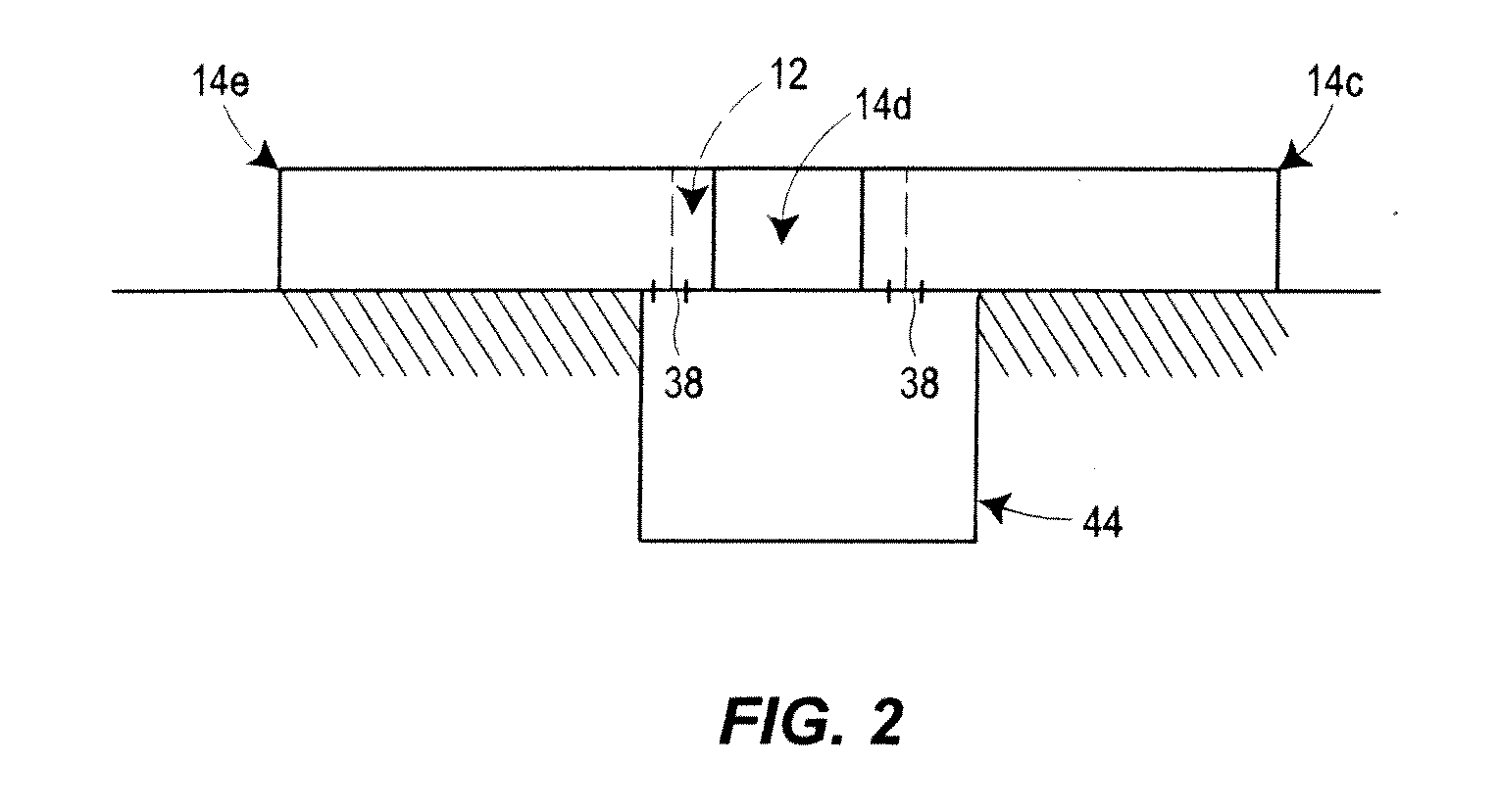
[0009]FIG. 2 is a side view of the manufacturing system of FIG. 1 including an optional drain and waste receptacle;

[0010]FIG. 3 is a plan view of another embodiment of a manufacturing system of the invention;

[0011]FIG. 4 is a plan view of another embodiment of a manufacturing system of the invention;

[0012]FIG. 5 is a plan view of another embodiment of a manufacturing system of the invention;

[0013]FIG. 6 is a side view of an optional upper docking collar; and

[0014]FIG. 7 is a plan view of another embodiment of a manufacturing system of the invention.

DETAILED DESCRIPTION

[0015]With reference to FIGS. 1 and 2, some embodiments of the manufacturing system 10 of the present disclosure comprise a core 12 and a plurality of movable manufacturing bays 14 disposed within an optional housing 16, as will be described in further detail below. In the embodiment depicted in FIG. 1, the system 10 includes first through sixth movable ...


PUM

PropertyMeasurementUnit
Timeaaaaaaaaaa
Areaaaaaaaaaaa

Abstract

A flexible, multi-product, multi-technology, expandable facility for manufacturing products, such as biologicals, pharmaceuticals, or chemicals, and manufacturing processes using elements of such a facility.

Description

CROSS-REFERENCE TO RELATED APPLICATIONS[0001]This is the U.S. national phase of International Patent Application No. PCT / US2009 / 069204, filed Dec. 22, 2009, and which claims priority to U.S. Provisional Patent Application No. 61 / 140,339, filed Dec. 23, 2008, and U.S. Provisional Patent Application No. 61 / 227,658, filed Jul. 22, 2009, the entire contents of each of which are hereby incorporated herein by reference.FIELD OF THE INVENTION[0002]The invention relates to a flexible, multi-product, multi-technology, expandable facility for manufacturing products, such as biologicals, pharmaceuticals or chemicals, and manufacturing processes using elements of such a facility.BACKGROUND[0003]Conventional manufacturing facilities for the production of biologicals, pharmaceuticals and chemicals (e.g., drugs) are typically designed for a specific type of product and utilize fixed production components and systems. Generally, different types of technologies or products, e.g. mammalian cell produ...

Claims


Application Information

Patent Timeline
IPC IPC(8): B23P17/00
CPCG05B19/4188G05B2219/31338B23P25/00Y10T29/51Y10T29/53096Y10T29/4998Y10T29/49Y10T29/534Y02P90/02E04H5/02G16H50/20G16H10/00G16C99/00C02F1/001E04B1/343E04B2001/0053
Inventor SCANNON, PATRICK J.BERNARD, FRANKTENEROWICS, ROBERT S.DADSON, JR., ALFRED C.
Owner XOMA US
Learn More