Toilet bowl flushing water tank device
a technology of flushing water tank and toilet bowl, which is applied in the direction of flushing devices, water installations, constructions, etc., can solve the problems of excessive increase in the supply quantity of flushing water and and achieve the effect of preventing wasteful discharge of flushing water
- Summary
- Abstract
- Description
- Claims
- Application Information
AI Technical Summary
Benefits of technology
Problems solved by technology
Method used
Image
Examples
first embodiment
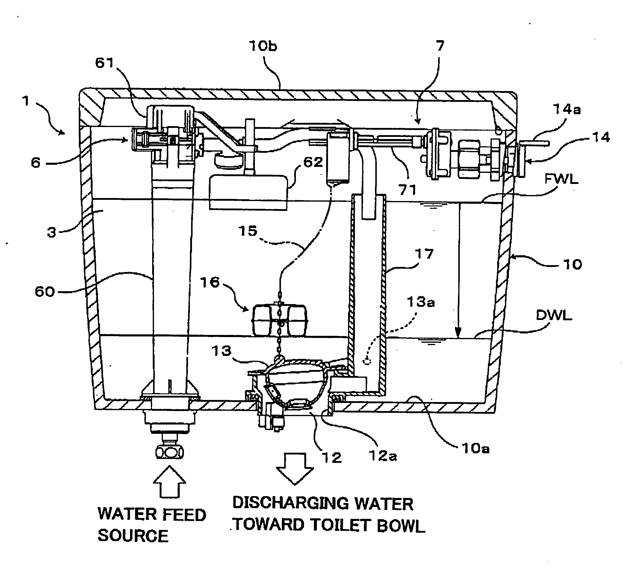
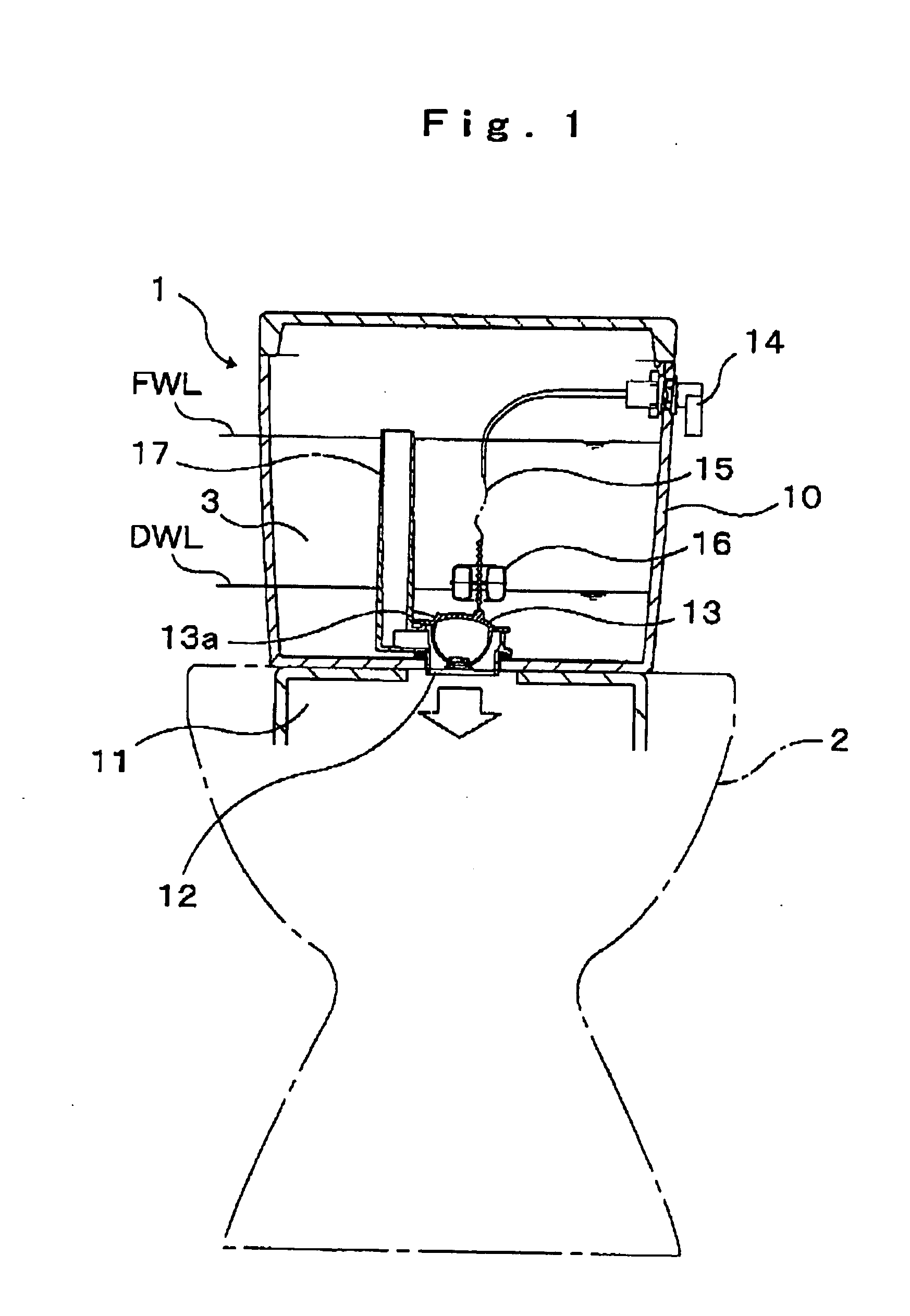
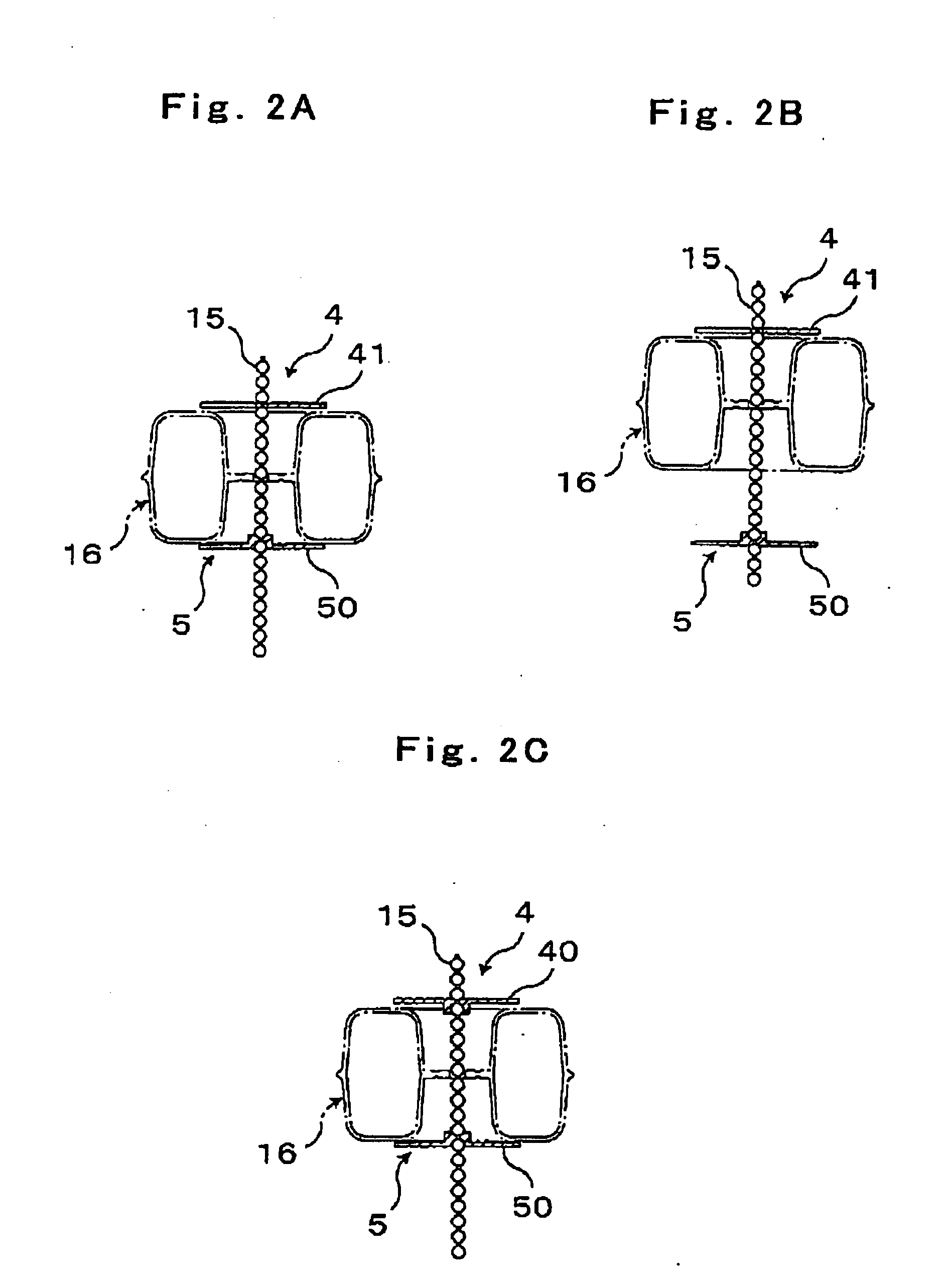
[0029]According to the above-mentioned constitution, as shown in FIG. 2A to FIG. 2E, in the toilet bowl flushing water tank device 1 according to the first embodiment 1, an upper engaging portion 4 and a lower engaging portion 5 for restricting a movable range of the float 16 are mounted on the connection member 15 formed of a ball chain. At least the lower engaging portion 5 includes a lower irreversible engaging jig 50 having physical irreversibility which prevents the removal of the lower engaging portion 5 from the connection member 15 unless broken.
[0030]In this embodiment, it is sufficient that the lower engaging portion 5 includes the lower irreversible engaging jig 50, and the upper engaging portion 4 may be formed of any engaging jig.
[0031]For example, the upper engaging portion 4 may be configured to include either one of an upper irreversible engaging jig 40 formed of the same member as the lower irreversible engaging jig 50 and having physical irreversibility which preve...
second embodiment
[0056]Next, a toilet bowl flushing water tank device according to a second embodiment of the present invention is explained in conjunction with FIG. 4A to FIG. 4C.
[0057]FIG. 4A to FIG. 4C are schematic explanatory views showing an arrangement state of a float in the toilet bowl flushing water tank device according to a second embodiment. In the same manner as the first embodiment explained above, a float 16 according to this embodiment is configured such that a center hole portion 16a which constitutes a recessed portion for allowing a connection member 15 to pass therethrough is formed in a center portion of the float 16.
[0058]Here, this embodiment differs from the embodiment described above with respect to a point that a lower irreversible engaging jig 50 and / or an upper irreversible engaging jig 40 are / is accommodated or arranged in such a center hole portion 16a.
[0059]That is, as shown in FIG. 4A to FIG. 4C, the float 16 is formed of a circular disc portion 16d in which a throu...
PUM
 Abstract
Description
Claims
Application Information
 - R&D
- Intellectual Property
- Life Sciences
- Materials
- Tech Scout
- Unparalleled Data Quality
- Higher Quality Content
- 60% Fewer Hallucinations
Browse by: Latest US Patents, China's latest patents, Technical Efficacy Thesaurus, Application Domain, Technology Topic, Popular Technical Reports.
© 2025 PatSnap. All rights reserved.Legal|Privacy policy|Modern Slavery Act Transparency Statement|Sitemap|About US| Contact US: help@patsnap.com


