Process for producing carbon nanotubes and carbon nanotubes produced thereby
a technology of carbon nanotubes and carbon nanotubes, which is applied in the direction of energy input, furniture, transportation and packaging, etc., can solve the problems of low yield, complicated control, and large volume of carbon nanotubes produced in a controlled manner, so as to improve the processing performance of these carbon nano-materials and reduce costs
- Summary
- Abstract
- Description
- Claims
- Application Information
AI Technical Summary
Benefits of technology
Problems solved by technology
Method used
Image
Examples
example i
[0078]A carbon nanotube formation process is used for producing carbon nanotubes from plant fiber using a cyclic heating carbon nanotube formation process.
[0079]In Five starting materials (including TMP fibers, purified lignin, filter paper, Avicel® cellulose, and α-cellulose) were used in this experiment. The individual samples were heated within a reaction vessel (such as, for example, in a ceramic tube in a Lindburg tube furnace). In the experiments herein the reaction vessel used was an aluminum end cap / sample insertion assembly that was attached to the open end of the ceramic tube in order to control the gas delivery and exit. All of the starting materials were initially preheated in air at about 21° C. for several hours under ambient pressure to form pre-treated fibers. The pre-treated fibers were then heated in a cyclical manner.
[0080]In certain embodiments, more than one heating cycle is used and fluctuating temperatures are used to heat the sample material in repeating cycl...
example ii
[0089]A carbon nanotube formation process is used for producing carbon nanotubes from plant fiber using a rapid heating, or flash, heating carbon nanotube formation process.
[0090]In this experiment, the reaction vessel comprised a quartz test tube, 1 inch in diameter and 8 inches in length, which was placed in a tube furnace previously heated to 1000° C. When the quartz tube temperature rose to about 1000° C., the sample (here, pretreated wheat stalk fibers) was added to the preheated reaction vessel. After about 5 to about 10 seconds, the quartz tube containing the sample was quickly removed from the heated tube furnace and cooled naturally to room temperature. In this example, the wheat stalk was pretreated by oven drying before the flash heating process.
[0091]Thus, in certain embodiments, the pre-heating temperature of the reaction vessel can be approximately the same as the rapid, or flash heating temperature. In other embodiments, the pre-heating temperature of the reaction ves...
example iii
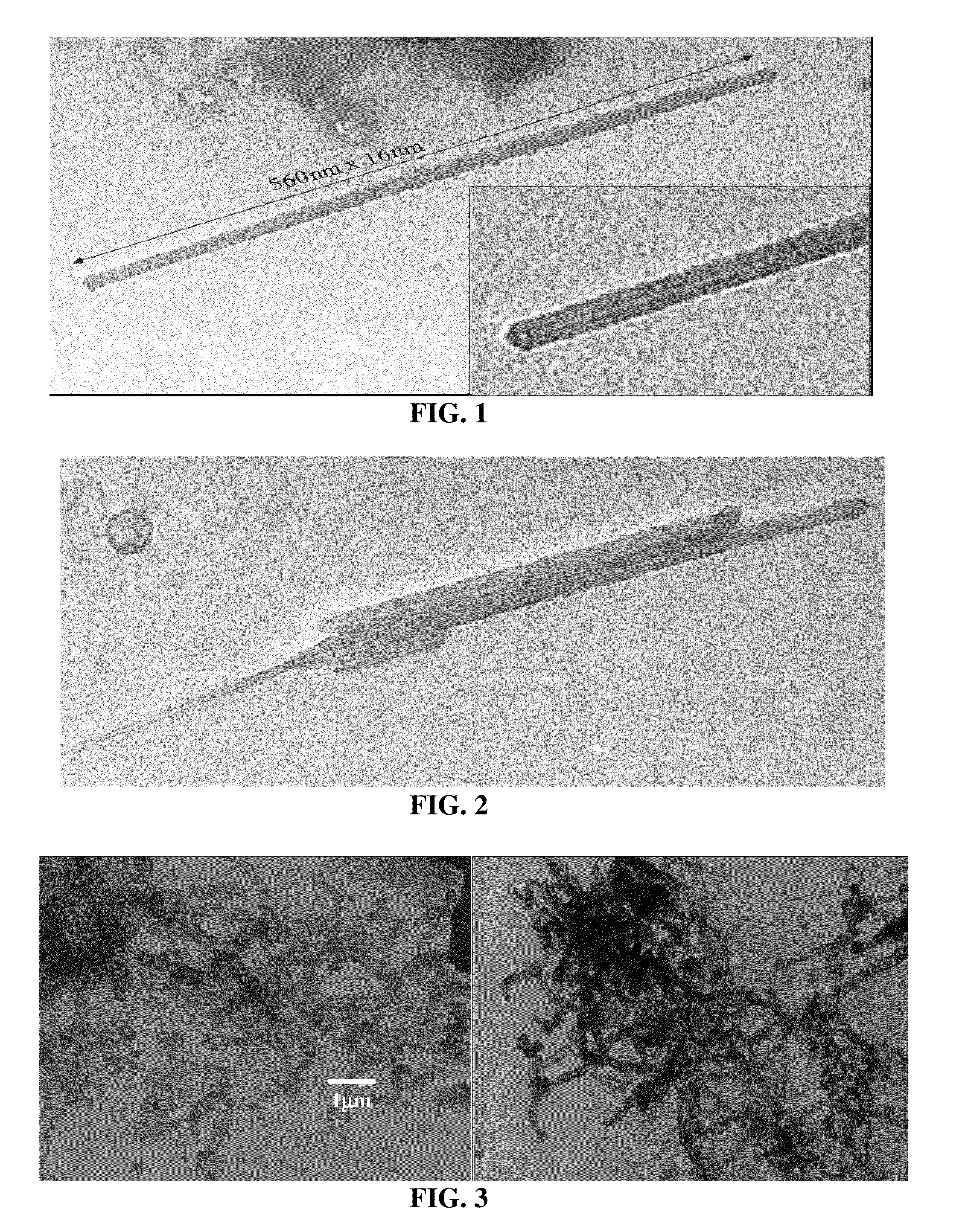
[0092]A carbon nanotube formation process is used with a suitable catalyst that is applied in solution to fiber samples. In the example herein the catalysts nickel chloride and iron chloride were used at 12% and 20% solution concentrations, respectively. About 3 drops of solution were used to soak 500 mg of oven-dried wheat stalk fiber samples. The catalyst treated fiber samples were then dried at about 105° C. for about 1 hour. The results showed that no carbon nanotubes were found in samples without catalyst. Also, no carbon nanotubes were found in the sample treated with iron chloride. However, the sample treated with nickel chloride was found to contain about 30% (by volume) carbon nanotubes, as can be seen in the TEMs in FIG. 3. In this example, while not wishing to be bound by theory, the inventors now believe that the mechanism for forming the carbon nanotubes involves the reduction of the nickel chloride catalyst to nanometer size nickel metal particles. The nanoparticles of...
PUM
| Property | Measurement | Unit |
|---|---|---|
| diameters | aaaaa | aaaaa |
| diameter | aaaaa | aaaaa |
| diameter | aaaaa | aaaaa |
Abstract
Description
Claims
Application Information
 - R&D
- Intellectual Property
- Life Sciences
- Materials
- Tech Scout
- Unparalleled Data Quality
- Higher Quality Content
- 60% Fewer Hallucinations
Browse by: Latest US Patents, China's latest patents, Technical Efficacy Thesaurus, Application Domain, Technology Topic, Popular Technical Reports.
© 2025 PatSnap. All rights reserved.Legal|Privacy policy|Modern Slavery Act Transparency Statement|Sitemap|About US| Contact US: help@patsnap.com


