
Compact Solid State Entangled Photon Source

a solid-state entangled photon and source technology, applied in the field of compact solid-state entangled photon sources, can solve the problems of large ar-ion, large system space occupied by laboratory optical tables, and large entanglement photon sources, and achieve the effect of high reflection coating

Active Publication Date: 2011-10-20
NGUYEN QUANT VIET
View PDF3 Cites 9 Cited by
  • Summary
  • Abstract
  • Description
  • Claims
  • Application Information

AI Technical Summary

Benefits of technology

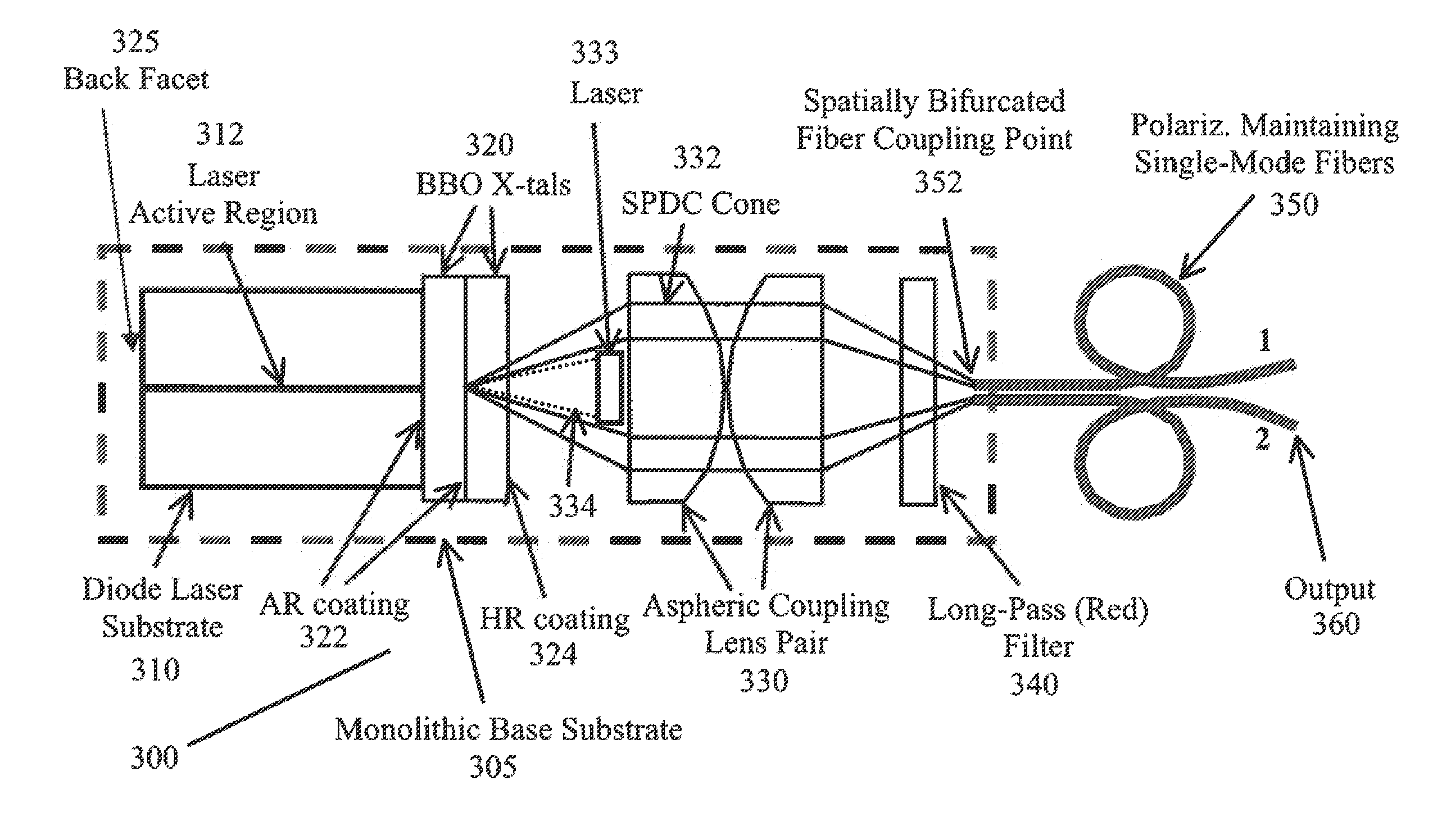
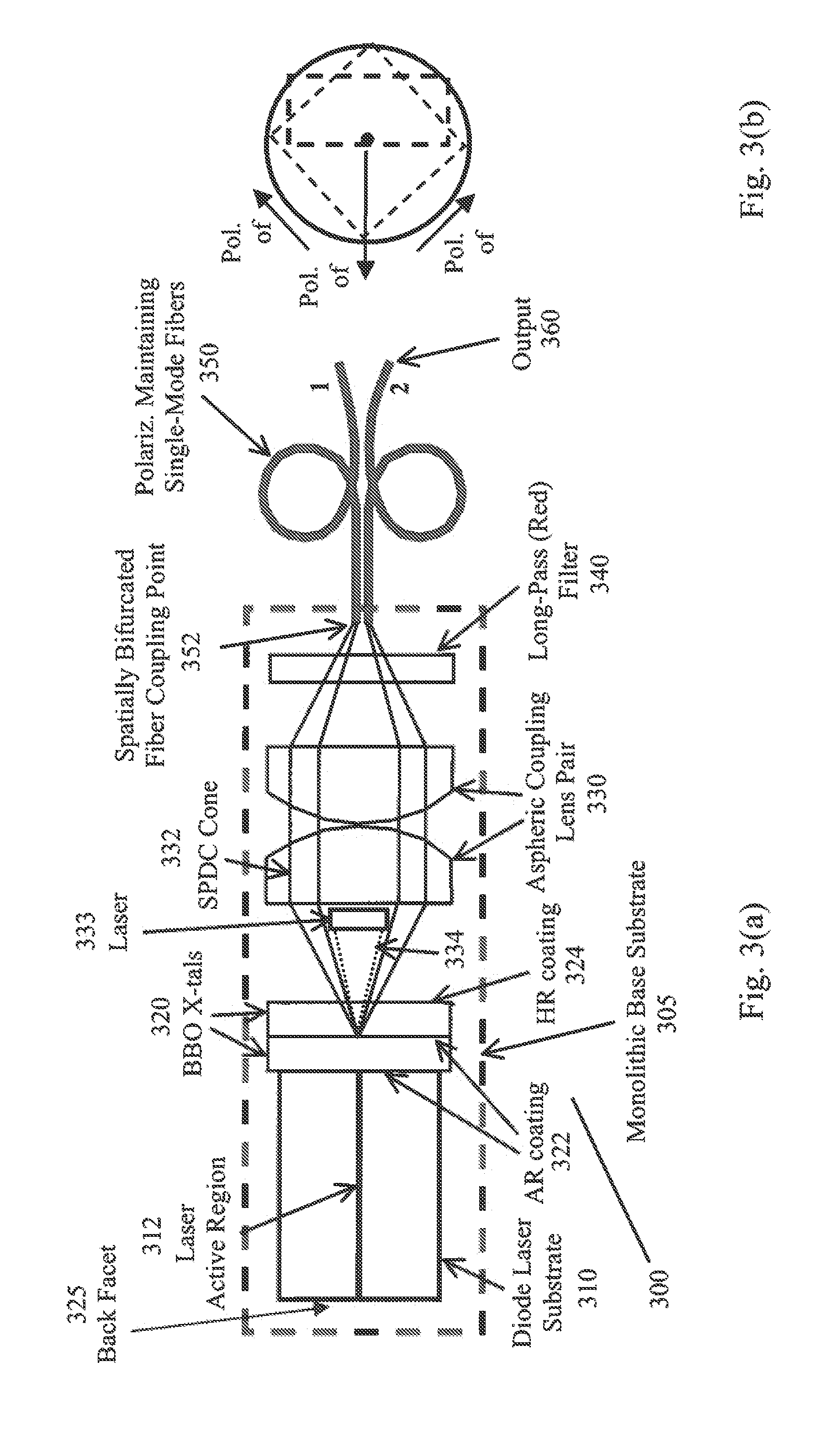
[0013]Additionally, the compact source may include a monolithic base to which the laser source, the pair of nonlinear crystals and the fiber coupling point are mounted. The source may also include a filter, positioned between the pair of nonlinear crystals and the fiber coupling point to filter light having a wavelength of the laser beam, wherein the filter can include at least one of a long-pass red glass filter, a laser stop and a dispersion element and/or a aspheric coupling lens pair, positioned between the pair of nonlinear crystals and the fiber coupling point to focus light produced through the spontaneous parametric down conversion of the laser beam. Also, the fiber coupling point may be configured to receive a pair polarization maintaining fibers.
[0014]Additionally, the opt...

Problems solved by technology

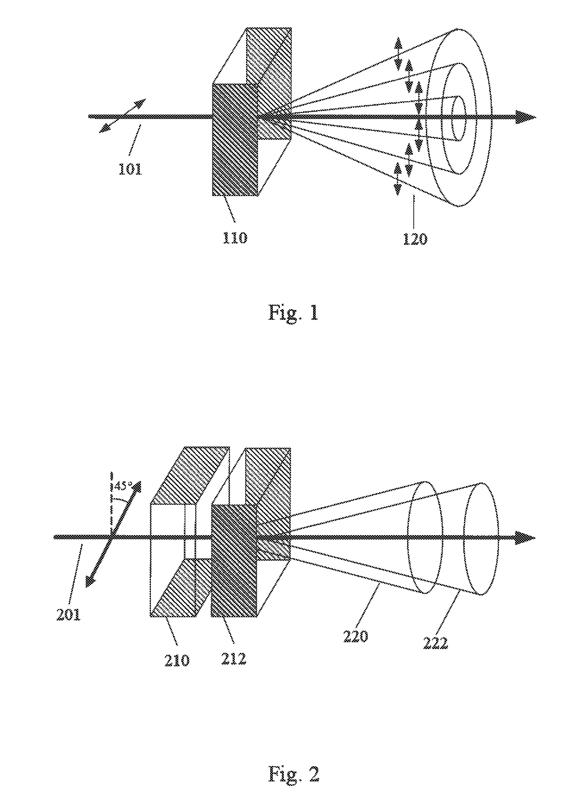
The problem up to now is that these sources of entangled photons require large, expensive and power-intensive Ar-ion lasers to generate light in the UV to pump a non-linear crystal, such as beta barium borate (BBC)), to produce spontaneous parametric down conversion (SPDC).
However, in the prior art, such systems typically take up a great deal of space on a laboratory optical table, weigh several hundreds of pounds and consume tens of kilowatts of electrical power and require cooling water.
Other problems of such systems are their rather inefficient conversion of electricity to usable QE photons.
One main problem with the prior art is that the systems are bulky and very power intensive.
Such prior art systems do not work well as a standard component in telecom, computer networking, field portable devices, or miniature nano-technology devices.
However, such a system still requires large macro-size optical components, is sensitive to optical alignment and is not portable.

Method used


Image

  • Compact Solid State Entangled Photon Source
  • Compact Solid State Entangled Photon Source
  • Compact Solid State Entangled Photon Source

Examples


Embodiment Construction

[0024]According to several embodiments, proposed designs for miniature, solid-state, sources of polarization and momentum, entangled photons that require very low power are described. Such source devices are critical components for the practical implementation of quantum communications, quantum cryptography, quantum key distribution, quantum computation, quantum imaging, quantum sensing, etc. As all of these emerging technologies have a distinct and immediate need for a compact and reliable source of high-brightness entangled photon pairs. Currently, there is no compact, rugged, field-deployable device on the market that can provide high-brightness entangled photon pairs while requiring only milliwatts of electrical power.

[0025]According to at least one embodiment, the present invention device will be able to produce a continuous source of approximately 80,000 to 8,000,000 polarization entangled photon pairs per second while requiring only milliwatts of electrical power. In preferre...


PUM


Abstract

A compact source of polarization-entangled photons includes a laser source, producing a laser beam, a pair of nonlinear crystals, in optical contact with each other, with one of the pair of nonlinear crystals having an input face, with the laser beam incident on the input face, and another of the pair of nonlinear crystals rotated 90°, along an axis perpendicular to the input face, with respect to each other and a fiber coupling point, configured to receive a pair of single-mode fibers. Pairs of polarization-entangled photons are produced through spontaneous parametric down conversion of the laser beam and provided to the fiber coupling point.

Description

CROSS-REFERENCE TO RELATED APPLICATIONS[0001]This application is a divisional of U.S. patent application Ser. No. 10 / 946,314, entitled COMPACT SOLID STATE ENTANGLED PHOTON SOURCE by the same inventor (Attorney's Docket No. 61011.00017) and having a filing date of Sep. 22, 2004.ORIGIN OF THE INVENTION[0002]The invention described herein was made by employees of the United States Government and may be manufactured and used by or for the Government for Government purposes without payment of any royalties thereon or therefore.BACKGROUND OF THE INVENTION[0003]1. Field of Invention[0004]The present invention relates to production of specific types of light with a high degree of fourth-order coherence that can be used in certain systems. In particular, the present invention is directed to methods for creating entangled photons and source for producing those entangled photons. More specifically, the present invention produces polarization-entangled photons. The entangled photons may be bene...

Claims


Application Information

Patent Timeline
IPC IPC(8): G02F1/39
CPCG02F2001/3507G02F1/39G02F1/3507
Inventor NGUYEN, QUANT-VIET
Owner NGUYEN QUANT VIET
Learn More