
Operation of patterned ultrasonic transducers

a transducer and ultrasonic technology, applied in the field of multiple element transducers, can solve the problems of unattractive commercial methods for moving a single focused region over the subject's body, limited focusing power of such transducers, and general cost of manufacturing of such transducers, so as to increase the efficacy of fat removal and be convenient to construct.

Inactive Publication Date: 2011-10-13
ULTRASHAPE INC
View PDF18 Cites 78 Cited by
  • Summary
  • Abstract
  • Description
  • Claims
  • Application Information

AI Technical Summary

Benefits of technology

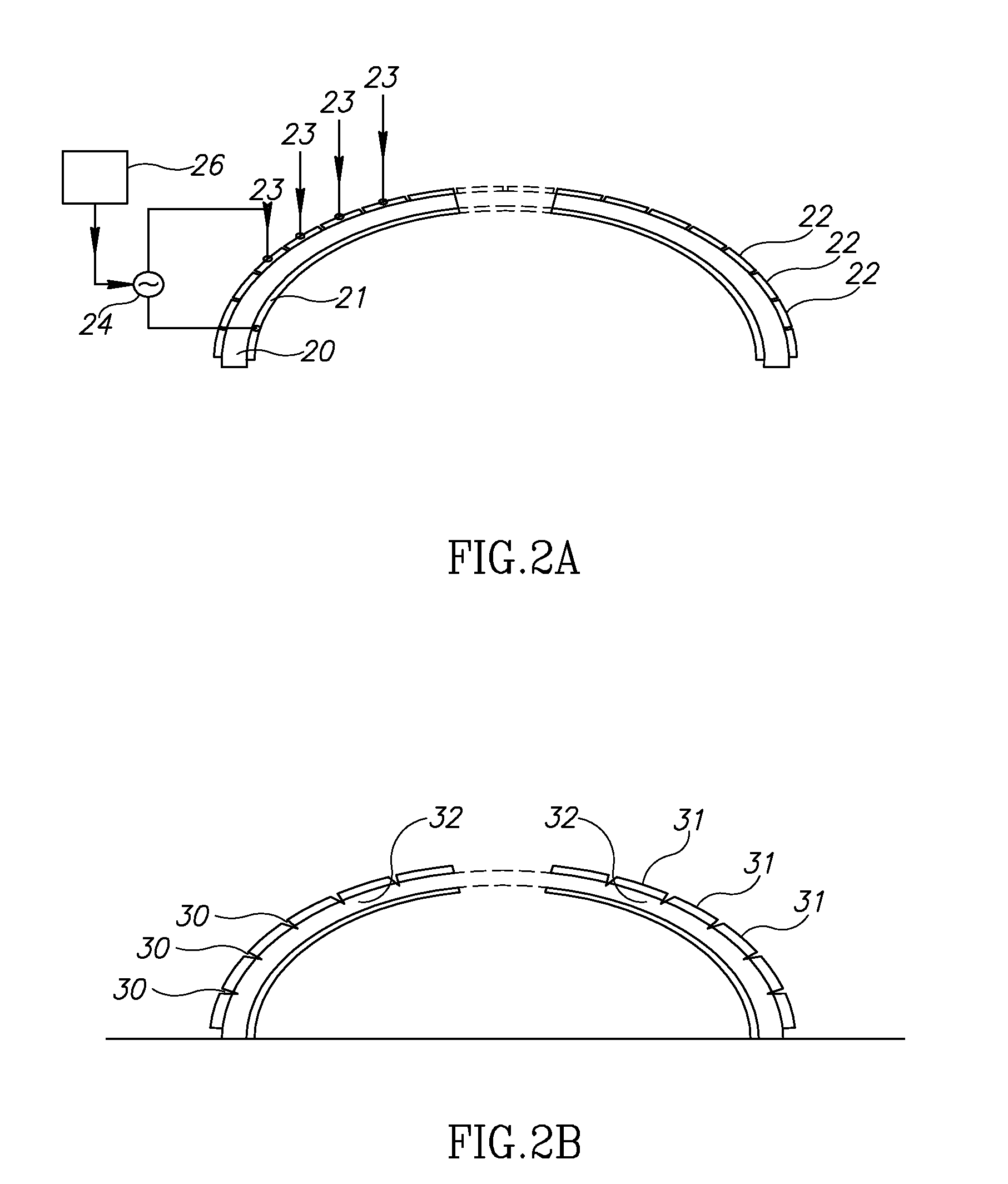
[0012]The present disclosure seeks to provide new uses for multiply segmented transducer heads, especially as applied to increasing the efficacy of fat removal. The methods are generally enabled by use of a segmented transducer structure, in which a single, unitary sample of piezoelectric material having two opposite surfaces is induced to operate as if it were composed of a plurality of smaller individual transducer segments, by means of electrically separate electrode elements applied to at least one surface of the two opposite surfaces, wherein each electrode element is associated with a transducer segment. The application of the electrode elements to the at least one surface can be performed either by dividing up a continuous electrode preformed on a surface of the material, generally by scribing or cutting the surface, or by applying a coating to the surface in the form of electrically separate electrode elements. Each of the separate electrode elements can then be activated separately by its own applied high frequency voltage, applied between the segment and an electrode on the opposing surface of the sample. Such a multi-element transducer has a structure which is simpler to construct than an adhesively assembled multi-element transducer, and which is also generally more reliable. Furthermore, the individual transducer segments generally operate independently of each other, and, except for some small effects on close neighbors, do not mutually interfere, thus enabling additive combinations of their outputs to be synthesized by appropriate excitation of the associated electrodes. According to some embodiments of the present disclosure, the single component base transducer can be constructed to have separate regions of different vibrational frequency when excited, and the electrodes arranged to overlie these separate regions, such that a multiple frequency ultrasound emission can be provided by exciting the separate electrode regions.
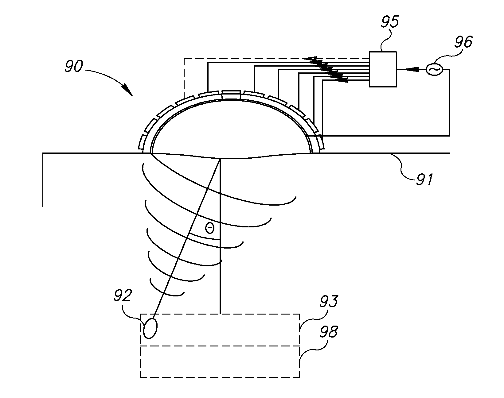
[0013]Different transducer segments, or different groups of transducer segments, or different samples of the piezoelectric material may be excited with high frequency voltages at different amplitudes and having different mutual phases, such that these segments or groups of segments, or samples, act as a phased array. Selection of the applied amplitudes and phases causes the transducer to emit ultrasound in a predetermined direction, or to sweep the emitted ultrasound through a predetermined range of directions. When used for treating a subject, this enables a larger region to be treated without moving the transducer head, so reducing the treatment time. Additionally, the focal position and size can be more accurately controlled, thus enabling safer operation in proximity to sensitive areas.

Problems solved by technology

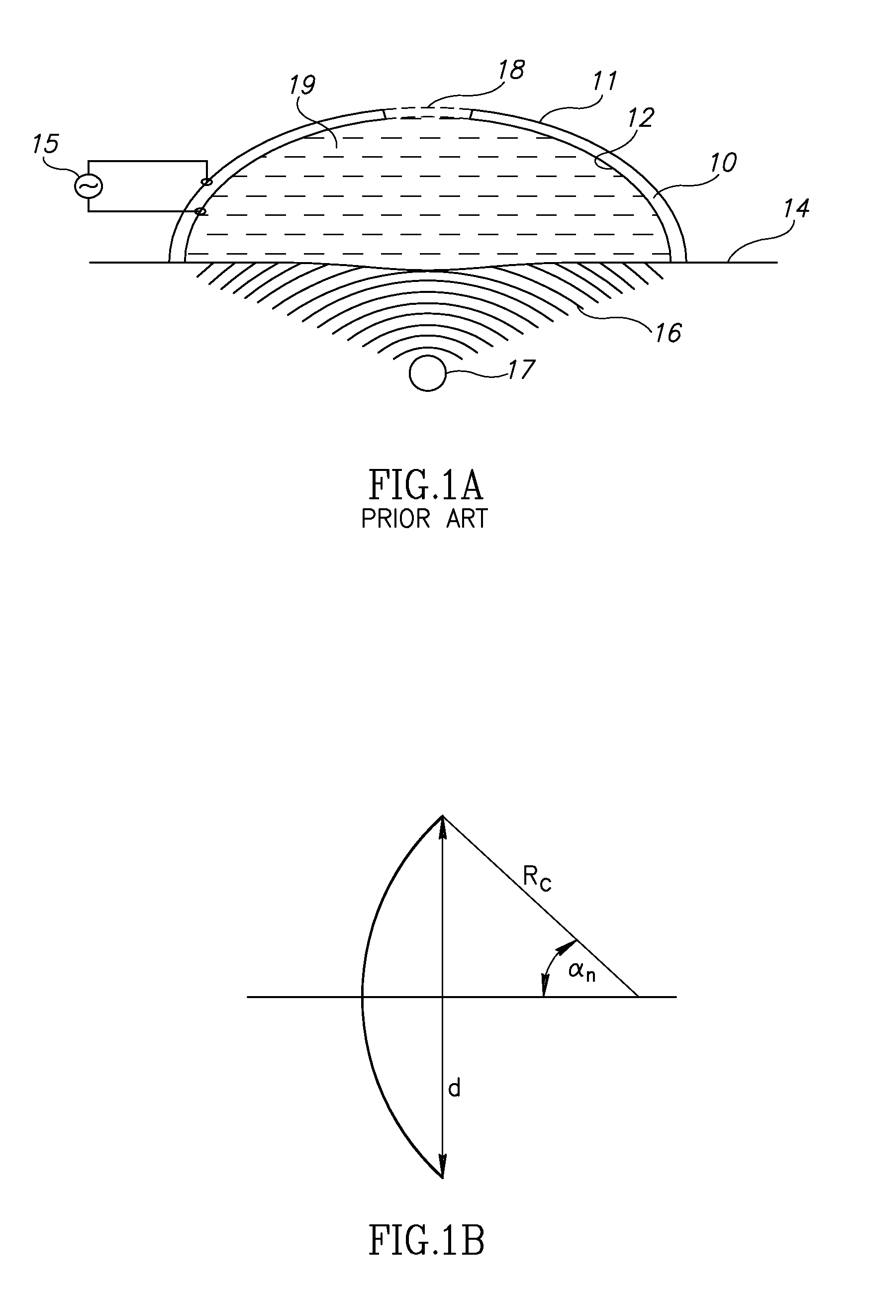
Furthermore, since cosmetic treatments in particular, and efficient apparatus utilization in general, are sensitive to the time taken to perform the procedure, methods whereby a singly focused region is moved over the subject's body are unattractive commercially, and better efficacy of such treatments would be desirable.
Other types of transducers are planar in shape, generating a sheet of energy at the target plane, but the focusing power of such transducers is limited.
However, transducers produced by such methods are generally costly to manufacture because of the labor intensive process of manufacture, and are often unreliable because of the susceptibility of the adhesive or epoxy matrix to loosen, degrade, or otherwise interfere with the transducers under the effects of high intensity ultrasound.

Method used


Image

  • Operation of patterned ultrasonic transducers
  • Operation of patterned ultrasonic transducers
  • Operation of patterned ultrasonic transducers

Examples


Embodiment Construction

Glossary

[0057]Below is presented a list of terms related to ultrasound equipment and ultrasonic output measurements which are used throughout the following disclosure:

[0058]As referred to herein, the term “Beam Axis” relates to a straight line joining the points of the maximum “Pulse Intensity Integral” measured at several different distances in the far field. This line is to be extended back to a transducer surface.

[0059]As referred to herein, the term “Beam Cross-Sectional Area” relates to the area on the surface of the plane perpendicular to the “Beam Axis” consisting of all points where the acoustic pressure is greater than 50% of the maximum acoustic pressure in the plane.

[0060]As referred to herein, the term “Duty Cycle (DC)” relates to the ratio of “Pulse Duration” to “Pulse Repetition Period”.

[0061]As referred to herein, the term “Focal Area” relates to the “Beam Cross-Sectional Area” on the “Focal Surface”.

[0062]As referred to herein, the term “Focal Surface” relates to the...


PUM


Abstract

A method for lysing fat cells using a multi-element, phased array piezoelectric transducer, the method comprising: providing a multi-element, phased array piezoelectric transducer comprising a single unitary piece of piezoelectric material having a plurality of electrode elements being formed as a segmented conductive layer on at least one surface of the piezoelectric material, each segment of the conductive layer being associated with an individual transducer element; positioning the transducer over a body of a patient, in proximity to a target volume containing fat cells; causing at least some of the transducer elements to emit ultrasound energy by exciting their associated electrode elements with high frequency voltages, the ultrasound energy having a power density at the target volume which is higher than a cavitation threshold; and spatially steering the ultrasound energy across the target volume by controlling the excitation of electrode elements in the time domain, thereby inducing cavitation in fat cells contained in the target volume.

Description

CROSS-REFERENCE TO RELATED APPLICATIONS[0001]This application is a continuation of U.S. patent application Ser. No. 12 / 081,379, filed Apr. 15, 2008, which claims the benefit of U.S. Provisional Patent Application No. 61 / 064,581, filed Mar. 13, 2008, both of which are incorporated herein by reference in their entirety.FIELD OF THE INVENTION[0002]The present disclosure relates to the field of the use of multiple element transducers for ultrasonic treatment of tissue.BACKGROUND OF THE INVENTION[0003]Ultrasound is widely used in medicine for diagnostic and therapeutic applications. Therapeutic ultrasound may induce a vast range of biological effects at very different exposure levels. At low levels, beneficial, reversible cellular effects can be produced, whereas at higher intensities, instantaneous cell death can occur. Accordingly ultrasound therapies can be broadly divided into two groups: “high” power and “low” power therapies. At the one end of the spectrum, high power applications ...

Claims


Application Information

Patent Timeline
Patent Type & Authority Applications(United States)
IPC IPC(8): A61N7/00H10N30/87
CPCA61N7/02A61N2007/0008B06B1/0637A61N2007/0078A61N2007/0095A61N2007/0065A61B8/4494A61B8/00
Inventor KUSHCULEY, LEONIDGOLAND, VLADIMIR
Owner ULTRASHAPE INC
Learn More