
Method for detecting defect in material and system for the method

a defect detection and material technology, applied in the field of material defect detection methods, can solve the problems of low detection accuracy of ccd camera methods for visually checking the surface of steel sheets, and many types of defects in steel sheets, etc., and achieve the effect of high accuracy

Active Publication Date: 2011-10-13
NIPPON STEEL CORP
View PDF21 Cites 16 Cited by
  • Summary
  • Abstract
  • Description
  • Claims
  • Application Information

AI Technical Summary

Benefits of technology

[0007]The present invention has been conceived based on consideration of the above problem. An object of the present invention is therefore to provide a method and system for detecting a defect both on the surface and in the surface layer of a material, such as a steel sheet, with high accuracy even if the material is moving or being transported.
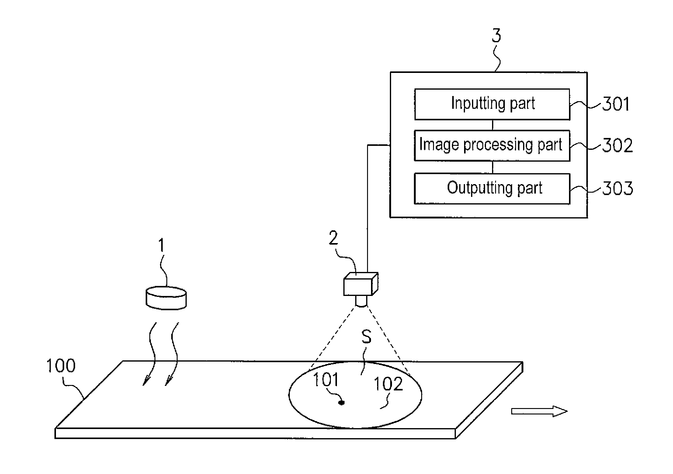
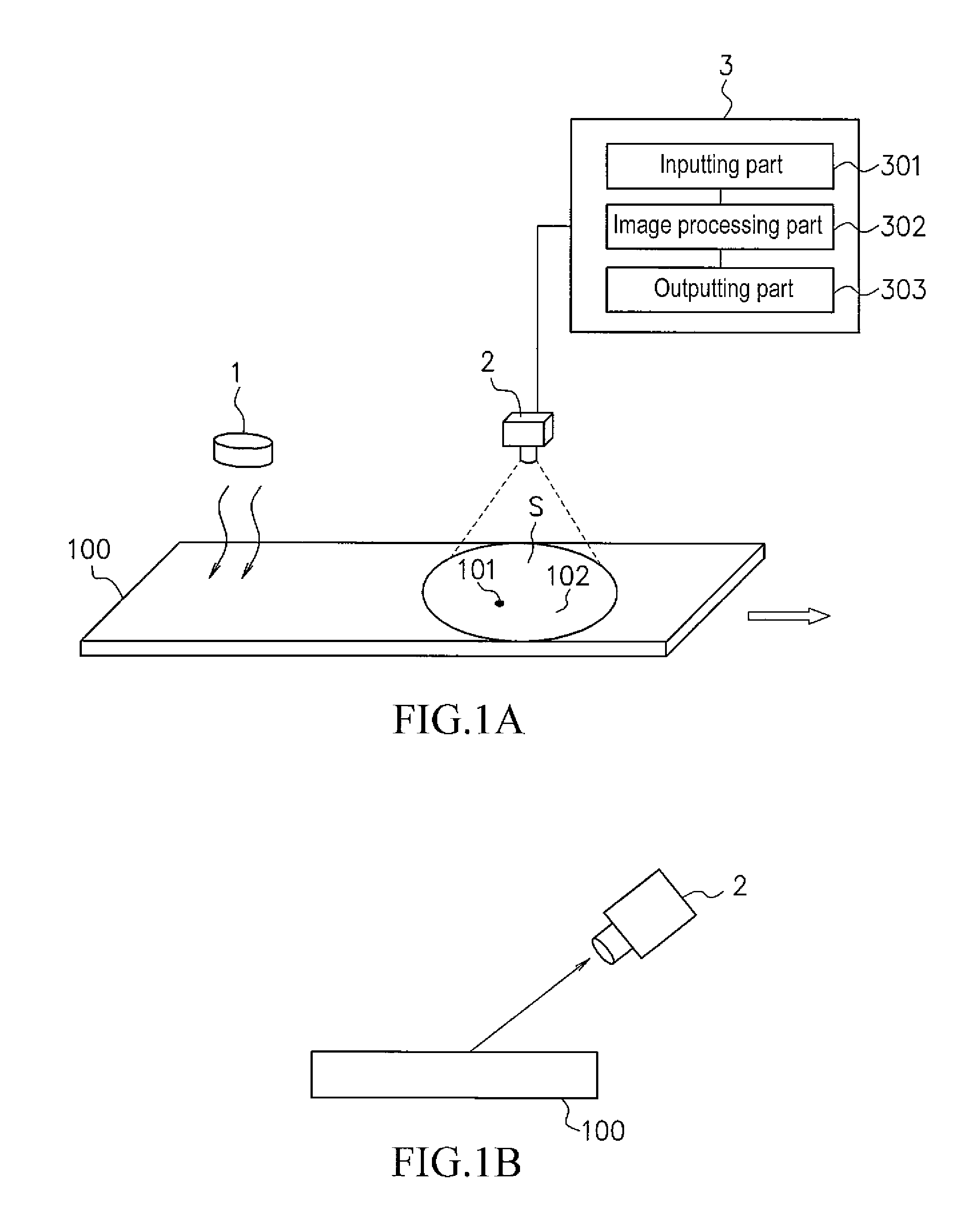
[0009]According to the present invention, the detection of a defect is carried out by: heating the surface of the material, obtaining thermal image data of the surface of the material using an infrared thermography camera while the material is being heated up at the heating step or being cooled down after being heated up, and detecting the defect by calculating Laplacian with respect to the temperature of the surface represented by the thermal image data. This makes it possible to detect the defect both on the surface and in the surface layer of the material with high accuracy even if the material is moving or being transported.

Problems solved by technology

In the case of steel sheet material, the steel sheet may have many types of defects such as a dent by the roll, a dross flaw formed by embedding a dross from hot dip galvanizing in the galvanized layer, blowholes scattered inside the steel sheet which are formed when argon gas is trapped in the cast metal during the casting process, or a surface defect caused by non-uniformity in the thickness of the galvanized layer.
Furthermore, the CCD camera method of visually checking the surface of a steel sheet does not have a high ability for detecting a defect located in the surface layer (not on the surface) since such a defect is often difficult to be visually recognized from outside.

Method used


Image

  • Method for detecting defect in material and system for the method
  • Method for detecting defect in material and system for the method
  • Method for detecting defect in material and system for the method

Examples


Embodiment Construction

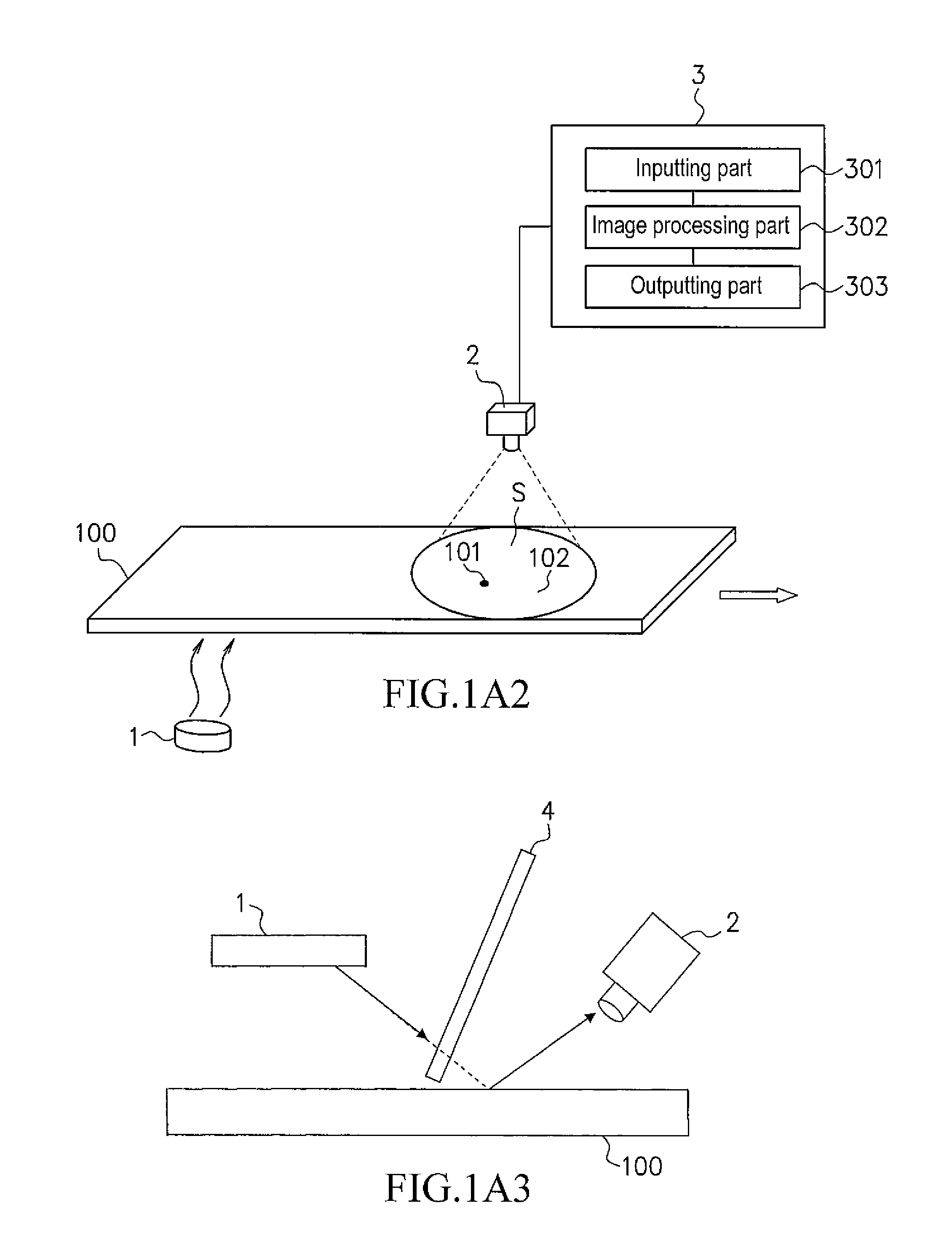
[0029]The present invention is more specifically set forth in the case of a steel sheet material in the following description with reference to the appended figures. As shown in FIG. 1A and FIG. 1C, the defect detecting system of the present invention has a heating device 1, an infrared thermography camera 2 and a detecting device 3, which detects a defect on the surface and / or in the surface layer (referred to as simply defect 101) of a steel sheet 100 (e.g., several mm in thickness).

[0030]A defect 101, the object to be detected in the invention, is described below with reference to FIGS. 3A-3D. There are many types of defects on the surface / in the surface layer of the steel sheet 100 and the shape of the defect can be, for example, as sort of scattered-sand, willow-leaf or spot.

[0031]A defect 101a in FIG. 3A is a defect caused by embedding some foreign material in the surface layer of the steel sheet 100, that is, e.g., a dross flaw formed by embedding a dross from hot dip galvani...


PUM


Abstract

A defect on the surface or in the surface layer of a moving material can be detected by using a method comprising steps of: heating the surface of the material, obtaining thermal image data of the surface of the material using an infrared thermography camera while the surface of the material is being heated up at the heating step or being cooled down after heating, and detecting the defect by calculating Laplacian with respect to temperature of the surface represented by the thermal image data. When the thermal image data is obtained while the material is being heated up, a heating device and the camera is arranged so that thermal energy emitted from the heating device is reflected by the material to come into the camera.

Description

FIELD OF THE INVENTION[0001]The present invention relates to a method for detecting a defect in a material and a system for the method suitable for detecting a defect on the surface and / or in the surface layer of the material.DESCRIPTION OF THE RELATED ART[0002]In the case of steel sheet material, the steel sheet may have many types of defects such as a dent by the roll, a dross flaw formed by embedding a dross from hot dip galvanizing in the galvanized layer, blowholes scattered inside the steel sheet which are formed when argon gas is trapped in the cast metal during the casting process, or a surface defect caused by non-uniformity in the thickness of the galvanized layer.[0003]Among these defects on a steel sheet, a defect of a difference in color from the other normal portions has been detected by operator's visual check.[0004]As shown in JP 2004-219177A, defect detecting technology is known, which can detect a defect of a steel sheet based on sheet surface image data taken by C...

Claims


Application Information

Patent Timeline
IPC IPC(8): G01N25/72
CPCG01N25/72
Inventor NAKAGAWA, JUNICHIITO, TADAYUKINISHIYAMA, TETSUODOKI, MASAHIROSAITO, KOZOGHARAIBEH, BELALCHUAH, KENG HOOSALAIMEH, AHMADYAMAMOTO, MASAHIROTAKEUCHI, TOMOYAITO, KAZUFUMIHUANG, HUAXIONGBOHUN, SEAN C.
Owner NIPPON STEEL CORP
Learn More