
Article of manufacture having a sub-surface friction stir welded channel

a technology of friction stir welding and friction stir, which is applied in the direction of manufacturing tools, cables, special-purpose vessels, etc., can solve the problems of communication loss, application that can be problematic, and deployment of conductor bundles in close proximity to moving parts, so as to reduce the placement error and scrap rate, reduce the cost and time, and reduce the effect of cost and tim

Inactive Publication Date: 2011-10-06
SMITH INT INC
View PDF26 Cites 22 Cited by
  • Summary
  • Abstract
  • Description
  • Claims
  • Application Information

AI Technical Summary

Benefits of technology

[0009]Exemplary embodiments of the present invention advantageously provide several technical advantages. For example, the present invention advantageously reduces the cost and time required to ‘wire’ a downhole tool. Moreover, the invention generally eliminates the need to gun drill long bores through the length of a downhole tool body. Eliminating such gun drilling steps tends to reduce placement error and scrap rates and thereby further reduce costs. The use of a friction stir welding process is further advantageous in that it generates a weld zone having superior hardness and wear resistance as compared to the tool body (and in particular as compared to conventional arc welding processes that generally result in a softening of the tool body).

Problems solved by technology

While the use of external conductors is adequate for many applications, there are applications that can be problematic.
For example, environmental exposure can cause corrosion and other degradation of the conductors which can in turn lead to communication loss.
Deployment of conductor bundles in close proximity to moving parts can also be problematic as the conductors may inadvertently engage the moving parts.
Transmission of data from a downhole tool to the surface is a difficulty common to many drilling operations.
While such ‘mud pulse telemetry’ techniques have long been commercially serviceable, they are also severely bandwidth limited (a typical mud pulse channel has a bandwidth on the order of about 1 to 20 bits per second).
This process is both expensive and time consuming.
Moreover, ensuring accurate placement of the bore along the entire length of the tool can be particularly problematic, especially in longer tools.
Errors in the gun drilling process can significantly increase scrap rates during machining of the outer body portion of the tool.
These increased scrap rates further increase the expense of the tool.

Method used


Image

  • Article of manufacture having a sub-surface friction stir welded channel
  • Article of manufacture having a sub-surface friction stir welded channel
  • Article of manufacture having a sub-surface friction stir welded channel

Examples


Embodiment Construction

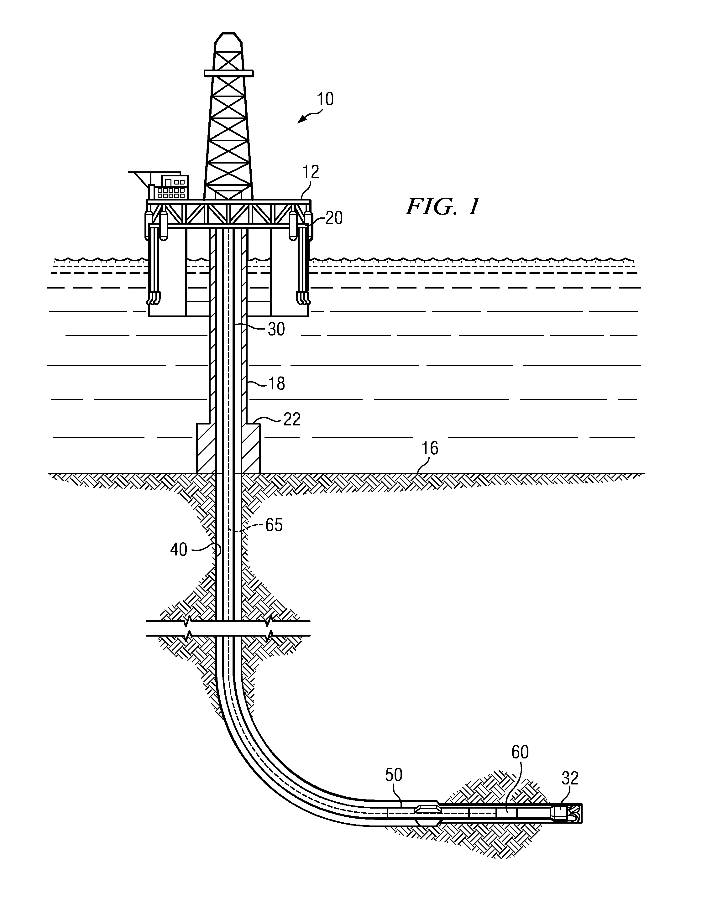
[0022]FIG. 1 depicts an exemplary offshore drilling assembly, generally denoted 10, suitable for deploying exemplary downhole tool embodiments in accordance with the present invention. In FIG. 1 a semisubmersible drilling platform 12 is positioned over an oil or gas formation (not shown) disposed below the sea floor 16. A subsea conduit 18 extends from deck 20 of platform 12 to a wellhead installation 22. The platform may include a derrick and a hoisting apparatus for raising and lowering the drill string 30, which, as shown, extends into borehole 40 and includes drill bit 32 at the distal end of the string. Drill string 30 is wired 65 thereby providing for direct electronic communication between a communications sub 60 deployed in the bottom hole assembly and the surface. The drill string 30 further includes a underreamer 50 deployed between communications sub 60 and the surface. Underreamer 50 has also been wired as indicated. Drill string 30 may optionally further include substan...


PUM

PropertyMeasurementUnit
Depthaaaaaaaaaa
Grain sizeaaaaaaaaaa
Lengthaaaaaaaaaa

Abstract

A method for routing an electrical conductor through a sub-surface channel in substantially any suitable metallic article of manufacture includes friction stir welding a cap in a groove formed in a surface of the article so as to form the sub-surface channel. An electrical conductor is then routed through the channel. The channel may further include a substantially tubular conduit formed therein with the electrical conductor being routed through the conduit. The friction stir weld zone formed during friction stir welding is generally harder and more wear resistant that the article body.

Description

RELATED APPLICATIONS[0001]This application claims the benefit of: (i) U.S. Provisional Application Ser. No. 61 / 319,850 entitled Friction Stir Welded Wire Channel for Downhole Tools, filed Mar. 31, 2010 and (ii) U.S. Provisional Application Ser. No. 61 / 393,605 entitled Friction Stir Welded Conduit Channel for Metal, filed Oct. 15, 2010.FIELD OF THE INVENTION[0002]The present invention relates generally to an article of manufacture having a friction stir welded channel. The invention further relates to methods for forming the friction stir welded channel. Particular embodiments of the invention relate to downhole tools (e.g., including drill pipe, underreamers, hole openers, and stabilizers) having a friction stir welded channel and methods for making the same.BACKGROUND OF THE INVENTION[0003]The use of electronic communications is ubiquitous. Such communications commonly require the routing of electrical conductors between multiple locations in an article of manufacture. For example,...

Claims


Application Information

Patent Timeline
IPC IPC(8): E21B10/32H02G1/06B32B1/08B32B15/00
CPCB23K20/122E21B10/32Y10T428/12403E21B17/1085Y10T29/49117E21B17/003E21B10/26
Inventor DAVIS, RICHARD
Owner SMITH INT INC
Learn More