
Drill assistance kit for implant hole in a bone structure

a bone structure and kit technology, applied in the field of kit for bone surgery, can solve the problems of high degree of precision, difficult to engage a precise drilling procedure, and difficult to drill a surgical hole, and achieve the effect of improving the general situation

Inactive Publication Date: 2011-09-29
POSITDENTAL
View PDF17 Cites 140 Cited by
  • Summary
  • Abstract
  • Description
  • Claims
  • Application Information

AI Technical Summary

Benefits of technology

[0012]The present invention overcomes the drawbacks given above and improves the general situation.
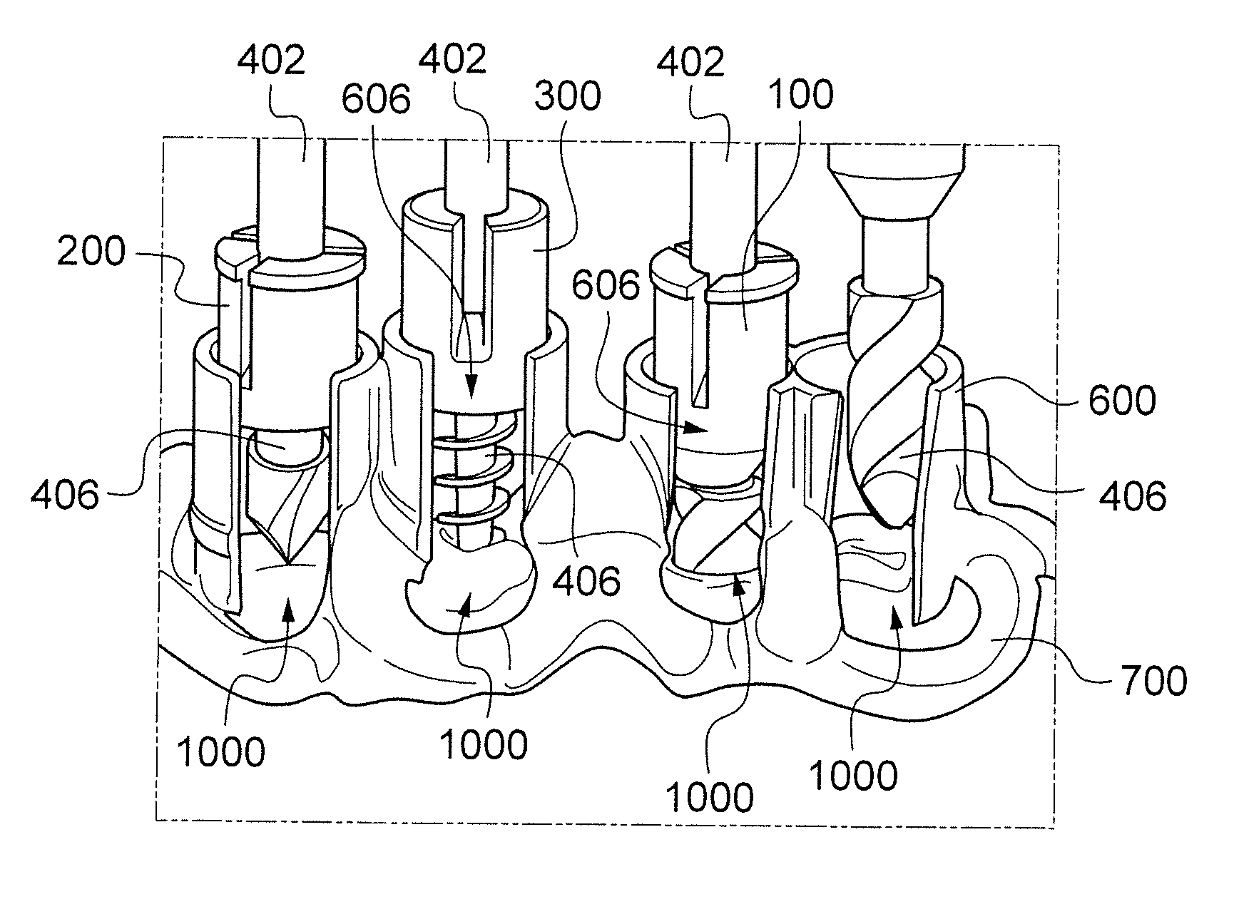
[0013]Particularly the present invention offers a great flexibility in drill exchange, overall visibility, broad access to the drilling site and sensitive control and regulation of the drilling procedure, including lateral positioning of the chirurgical drill and precise axial orientation of the latter during drilling.

Problems solved by technology

Drilling of chirurgical holes is known to be a delicate procedure that needs a high degree of precision.
Furthermore, drilling procedures are known to be delicate because they can lead to permanent lesions.
This leads to the fact that the physiological drilling sites are often damaged which makes it even more difficult to engage a precise drilling procedure.
However, many of the above cited drawbacks are not overcome by this drill guide, including visibility issues and / or dust evacuation for example.
None of the known prior art solutions is able to overcome properly the above cited drawbacks.

Method used


Image

  • Drill assistance kit for implant hole in a bone structure
  • Drill assistance kit for implant hole in a bone structure
  • Drill assistance kit for implant hole in a bone structure

Examples


Embodiment Construction

[0053]First it has to be noted that the present invention partially involves a foregoing tomographic method that comprises collecting of tomographic data that are representative of an anatomical zone. These data are mainly used to provide a foot structure (according to a homologous pattern such as a jaw bone structure for example) of the base frame of the present invention (see below for more details). This method is described in detail in the patent application U.S. Ser. No. 12 / 602,634 which is incorporated herein by reference.

[0054]Also, it has to be noted that the present invention is described with reference to a dentistry procedure. It has to be understood that the present invention is particularly adapted for this kind of procedure but can however be used in other fields of chirurgical procedures.

[0055]Further, it has to be noted that In the present description the wording “jaw bone”, “jaw bone structure”, “upper jaw bone” or “lower jaw bone” designate the entire maxilla, incl...


PUM


Abstract

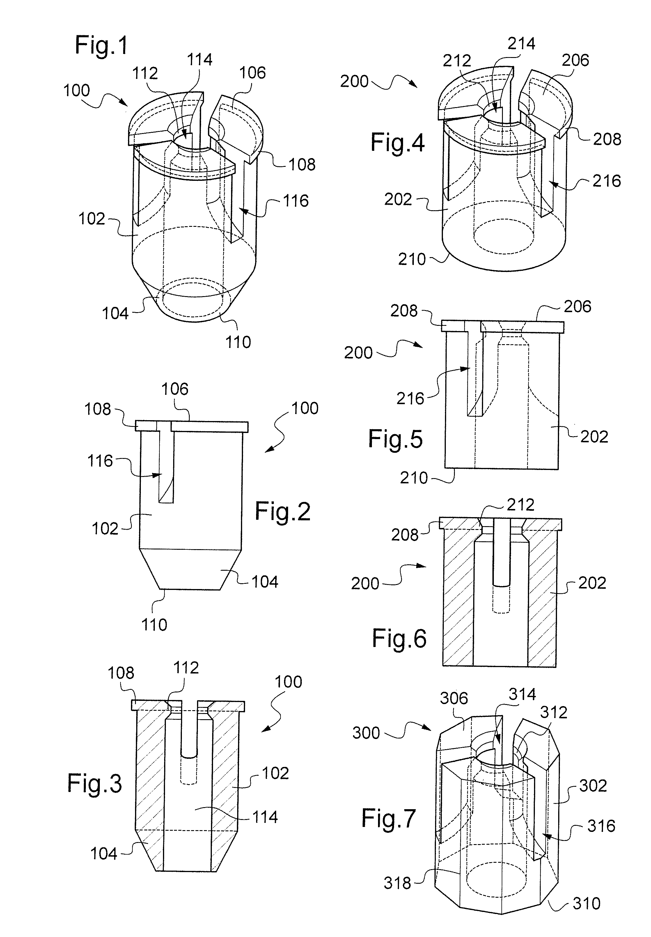
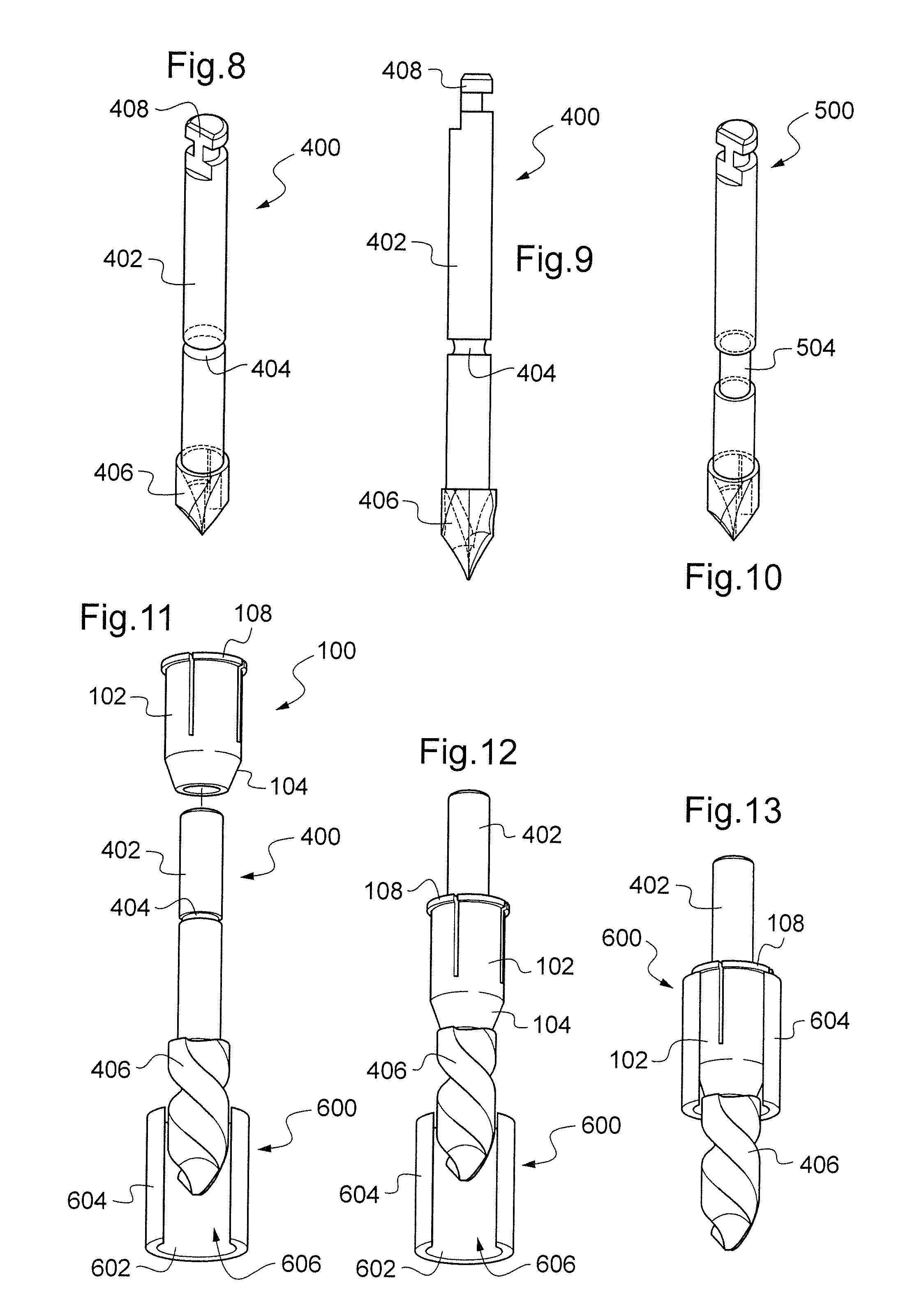
The present invention provides a kit for bone surgery comprising a chirurgical drill and a base frame for positioning of said drill on an anatomical part of a patient. The base frame comprises at least one guiding tube with a cylindrical inner surface of predetermined diameter and also comprises a longitudinal cutout for direct view of the drilling site. The kit further comprises a burr-ring with a cylindrical outer surface of predetermined diameter arranged to be placed around the chirurgical drill. The diameter of the cylindrical outer surface of the burr-ring is slightly less than the diameter of the cylindrical inner surface of the guiding tube such that the burr-ring and the guiding tube are at most in a two-degree of freedom relationship along the longitudinal axis of the guiding tube when the burr-ring is engaged in the guiding tube. The invention also provides a bone surgery method using the kit.

Description

TECHNICAL FIELD[0001]The present invention relates to a kit for bone surgery. More particularly, the present invention relates to a drill kit suitable for instance for the assistance of drilling a hole in a jaw bone structure for dental implants.BACKGROUND OF THE INVENTION[0002]Drilling of chirurgical holes is known to be a delicate procedure that needs a high degree of precision. Each hole must be drilled precisely with regard on the depth and on the axial orientation of the chirurgical drill. This is particularly the case when it comes to chirurgical procedures that implicate a subsequent implant.[0003]During chirurgical drilling procedures, drills often have to be exchanged. For example, some drilling procedures comprise several distinct steps in order to slowly enlarge the hole in which an implant is eventually placed. This implicates distinct drills of increasing diameters. Other drilling procedures use drills of different nature. Some procedures use specialized miniature percu...

Claims


Application Information

Patent Timeline
Patent Type & Authority Applications(United States)
IPC IPC(8): A61B17/56
CPCA61C1/084
Inventor FERNANDEZ-SCOMA, ALAIN
Owner POSITDENTAL
Learn More