
Semiconductor ceramic and positive temperature coefficient thermistor

Active Publication Date: 2011-09-29
MURATA MFG CO LTD
View PDF5 Cites 5 Cited by
  • Summary
  • Abstract
  • Description
  • Claims
  • Application Information

AI Technical Summary

Benefits of technology

[0023]The semiconductor ceramic of the present invention includes a BamTiO3-based composition, as a main component, having a perovskite structure represented by general formula AmBO3, wherein part of Ba constituting the A site is replaced with Na, Bi, Ca, and a rare-earth element having an ionic radius smaller than that of the Na; the content of the rare-earth element when the total number of moles of the elements constituting the A site is 1 mole is 0.0005 to 0.015 on a molar basis; and the content of the Ca when the total number of moles of the elements constituting the A site is 1 mole is 0.05 to 0.20 (preferably 0.125 to 0.175) on a molar basis. Therefore, there can be provided a semiconductor ceramic in which the degradation of resistance over time can be suppressed even when the semiconductor ceramic is exposed to high-humidity for a long time.
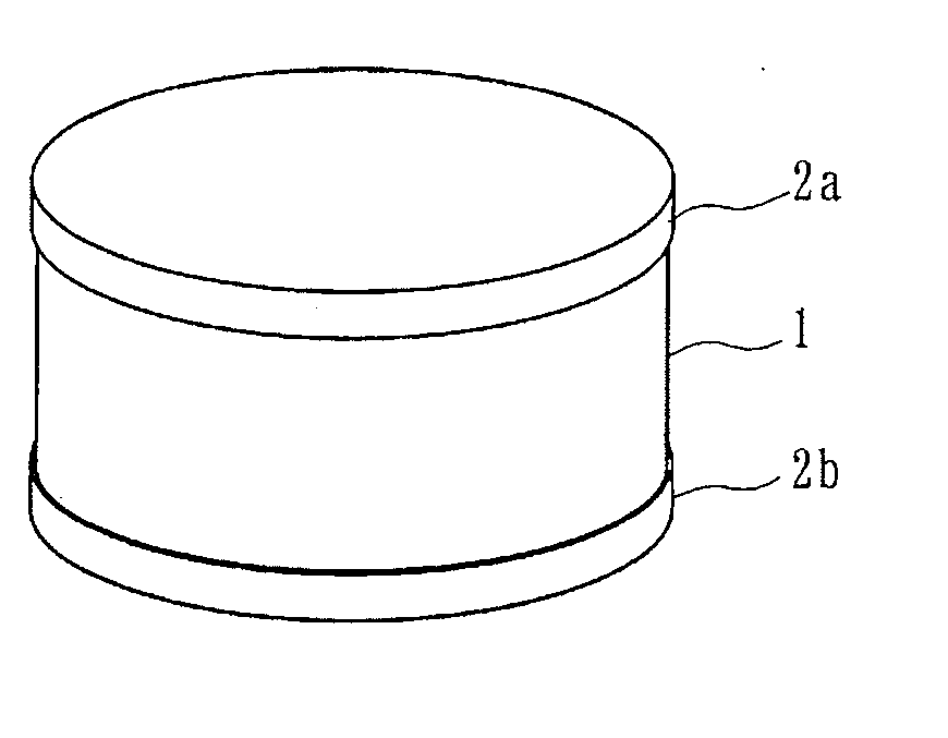
[0024]The PTC thermistor of the present invention includes a component body and a pair of outer electrodes formed on surfaces of the component body, wherein the component body is formed of the semiconductor ceramic described above. Therefore, there can be provided a PTC thermistor having high reliability.
[0025]Specifically, there can be provided a lead-free PTC thermistor that has high reliability and in which the percentage change in resistivity can be suppressed to 30% or less even when the PTC thermistor is kept in a high-humidity atmosphere of 85% RH for 1000 hours.

Problems solved by technology

As a result, a current does not easily flow and the temperature is decreased.
However, Pb is an environmentally unfriendly substance and thus, in consideration of environment, the development of a lead-free semiconductor ceramic that substantially does not contain Pb has been demanded.

Method used


Image

  • Semiconductor ceramic and positive temperature coefficient thermistor
  • Semiconductor ceramic and positive temperature coefficient thermistor
  • Semiconductor ceramic and positive temperature coefficient thermistor

Examples


Embodiment Construction

, various samples containing Dy (molar ratio: 0.002) as the rare-earth element Ln and obtained by changing the molar amount y of Ca were prepared, and the characteristics were evaluated.

[0090]BaCO3, CaCO3, Na2CO3, Bi2O3, TiO2, and Dy2O3, which were raw materials of a main component, were prepared and then weighed and mixed to obtain a mixed powder so that the sintered body had the composition shown in Table 3.

[0091]After that, sample Nos. 11 to 19 were prepared by the same method and process as those in Example 1 but the firing process was performed in a nitrogen atmosphere whose oxygen concentration was 5000 ppm by volume.

[0092]Regarding the sample Nos. 11 to 19, the electrical resistivity ρ0 at 25° C. (room temperature), the number of digits of PTC ΔR, the Curie temperature Tc, and the percentage change in resistivity Δρ / ρ0 were determined by the same method and process as those in [Example 1].

[0093]Table 3 shows the compositions and measurement results of the sample Nos. 11 to 19...


PUM

PropertyMeasurementUnit
Substance countaaaaaaaaaa
Temperatureaaaaaaaaaa

Abstract

A semiconductor ceramic includes a BamTiO3-based composition, as a main component, having a perovskite structure represented by general formula AmBO3, wherein part of Ba constituting the A site is replaced with Na, Bi, Ca, and a rare-earth element having an ionic radius smaller than that of the Na; the content of the rare-earth element when the total number of moles of the elements constituting the A site is 1 mole is 0.0005 to 0.015 on a molar basis; and the content of the Ca when the total number of moles of the elements constituting the A site is 1 mole is 0.05 to 0.20 (preferably 0.125 or more and 0.175 or less) on a molar basis. A PTC thermistor includes a component body 1 formed of the semiconductor ceramic. Accordingly, high reliability is achieved even if an alkali metal element is present.

Description

[0001]This is a continuation of application Serial No. PCT / JP2009 / 0070760, filed Dec. 11, 2009, the contents of which is incorporated herein by reference.TECHNICAL FIELD[0002]The present invention relates to a semiconductor ceramic and a positive temperature coefficient thermistor, and specifically to a semiconductor ceramic having a positive temperature coefficient (hereinafter referred to as “PTC characteristic”) and a positive temperature coefficient thermistor (hereinafter referred to as “PTC thermistor”) used for heaters or the like.BACKGROUND ART[0003]A barium titanate (BaTiO3)-based semiconductor ceramic generates heat as a result of application of a voltage and has PTC characteristics in which the resistance value rapidly increases when the temperature exceeds the Curie temperature Tc at which a phase transition from a tetragonal crystal to a cubic crystal takes place.[0004]In such a semiconductor ceramic having PTC characteristics, the resistance value increases when the te...

Claims


Application Information

Patent Timeline
IPC IPC(8): H01C7/02H01B1/02
CPCC04B35/46C04B35/4682C04B2235/3201C04B2235/3208C04B2235/3224H01C7/025C04B2235/3227C04B2235/3262C04B2235/3298C04B2235/6584C04B2235/79C04B2235/3225
Inventor ABE, NAOAKIKATSU, HAYATOGOTO, MASATOKISHIMOTO, ATSUSHINAKAYAMA, AKINORI
Owner MURATA MFG CO LTD
Learn More