
Power supply device having precharging function

a power supply device and function technology, applied in the direction of battery/cell propulsion, electric energy management, transportation and packaging, etc., can solve the problems of large amount of charge current melting, unable to disconnect the driving battery from the load, and damage to the contact of the relay, so as to reduce the on resistance reduce the heat generation of the semiconductor switching element, and quickly pre-charge

Inactive Publication Date: 2011-09-29
SANYO ELECTRIC CO LTD
View PDF7 Cites 33 Cited by
  • Summary
  • Abstract
  • Description
  • Claims
  • Application Information

AI Technical Summary

Benefits of technology

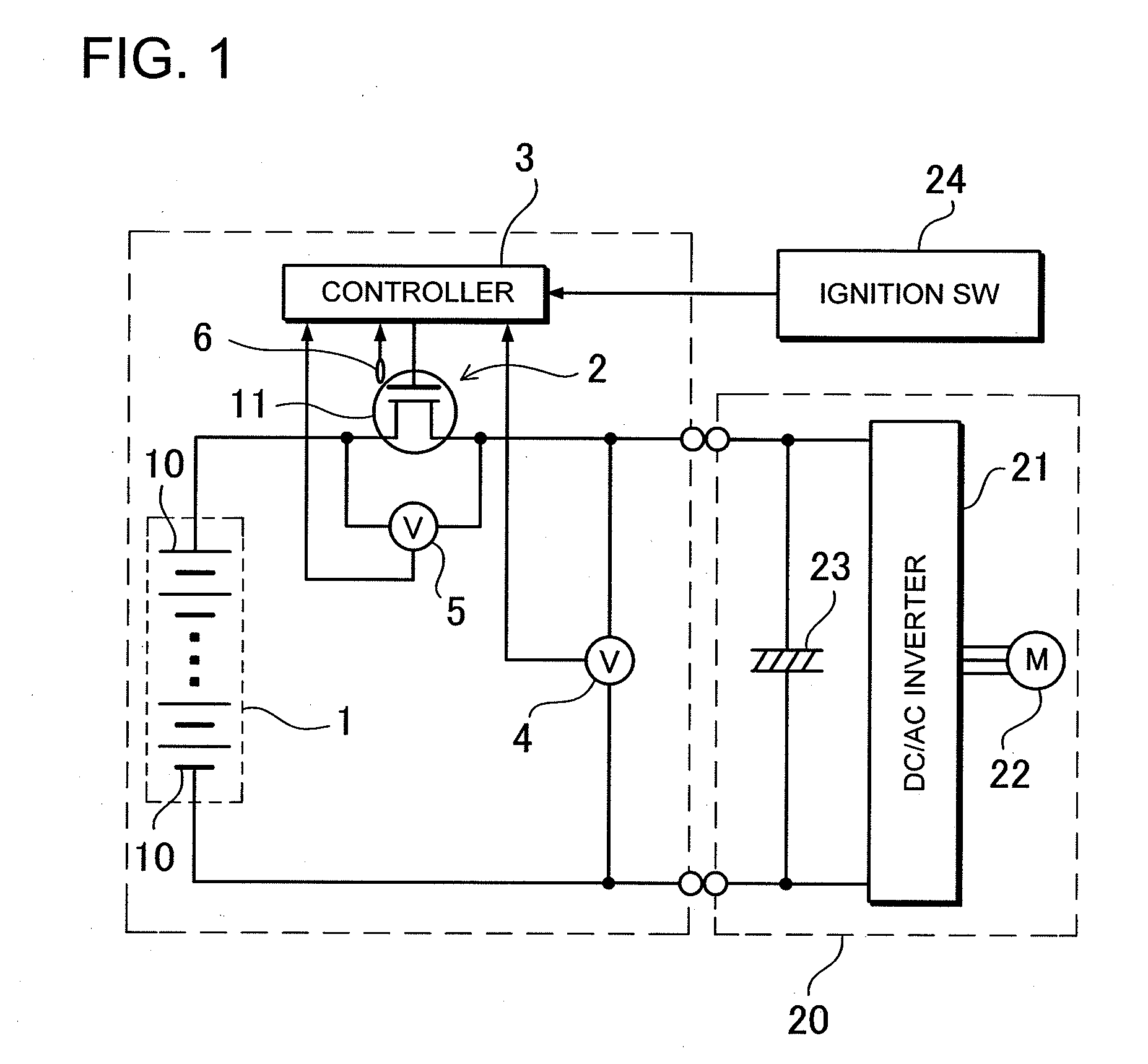
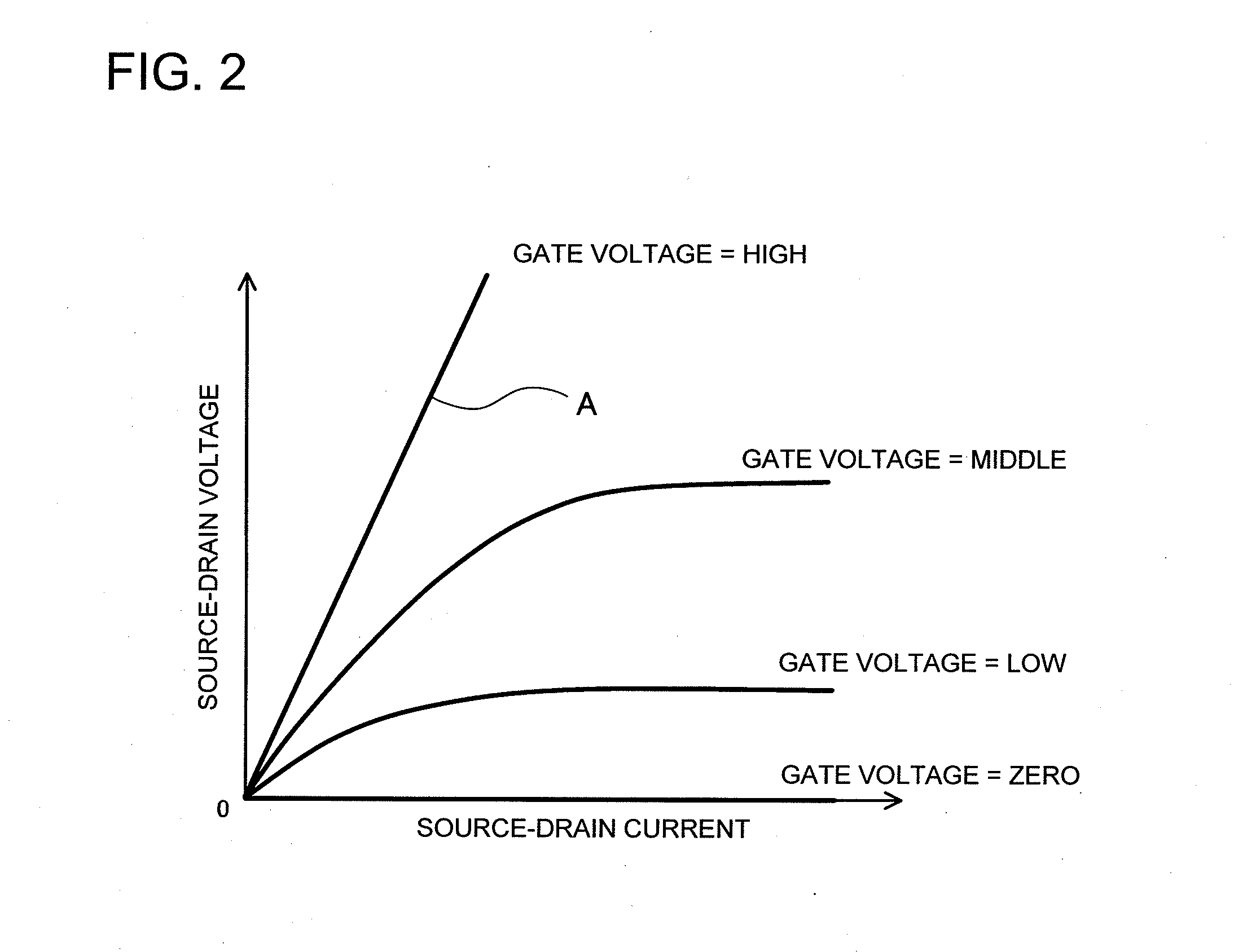
In the power supply device according to the present invention, the control circuit 3 gradually reduces the ON resistance of the semiconductor switching element 11 when the parallel capacitor 23 of the load 20 is precharged.
Also, in the power supply device, even if the thyristor cannot be turned OFF when the current does not flow through the load, the current flowing through the thyristor can be cut off by pulling out the service plug so that the thyristor can be turned OFF. Therefore, it is possible to improve the safety of the power supply device that employs the thyristor.

Problems solved by technology

This may cause damage to the contact of the relay.
In particular, a large amount of charge current may melt and close the contact of the relay.
If the contact is closed when melting, the relay cannot be turned OFF so that the driving battery cannot be disconnected from the load.
In addition, the voltage of the driving battery is high.
For this reason, an expensive FET is required that can operate at high voltage and a large amount of current.
As a result, the component cost will be high.

Method used


Image

  • Power supply device having precharging function
  • Power supply device having precharging function
  • Power supply device having precharging function

Examples


Embodiment Construction

)

The following description will describe embodiments according to the present invention with reference to the drawings.

The vehicle power supply device shown in FIG. 1 is installed in a vehicle such as hybrid car, fuel-cell vehicle, and electric vehicle. The power supply device drives an electric motor 22 of a vehicle-side load 20 for vehicle running. The electric motor 22 of the vehicle-side load 20 is connected to a driving battery 1 through a DC / AC inverter 21. The DC / AC inverter 21 converts direct current from a vehicle-driving battery 1 into three-phase alternating current, and controls power supplied to the electric motor 22. The DC / AC inverter supplies electric power to the electric motor at increased voltage or without increasing voltage.

This illustrated power supply device includes an output switch 2 that connects the driving battery 1 to the vehicle-side load 20. The connection of output switch 2 is controlled by a control circuit 3. The control circuit 3 turns the output s...


PUM


Abstract

A power supply device includes a battery 1, an output switch 2 connecting the battery 1 to a load 20, and a control circuit 3 controlling the output switch 2. The output switch 2 is a semiconductor switching element 11 having controllable ON resistance. In the power supply device, the ON resistance of the semiconductor switching element 11 is controlled by the control circuit 3 so that the ON resistance in a precharge state is set larger than the ON resistance in an electrically-conducted state. The parallel capacitor 23 of the load 20 is precharged in the precharge state. After the parallel capacitor 23 of the load 20 is precharged, the load 20 is supplied with power from the battery 1 with the semiconductor switching element 11 being brought into the electrically-conducted state in which the ON resistance of the semiconductor switching element 11 is smaller than the precharge state.

Description

BACKGROUND OF THE INVENTION1. Field of the InventionThe present invention relates to a power supply devices such as vehicle power supply device that connects a driving battery for driving a vehicle to a vehicle-side load through an output switch, and in particular to a power supply device that, after precharging a parallel capacitor of a vehicle-side load, brings an output switch into an electrically-conducted state and supplies electric power from a driving battery to the vehicle-side load.2. Description of the Related ArtVehicle power supply devices have a relay connected to the output side of a driving battery. In the power supply devices, the relay is turned ON so that the driving battery is connected the vehicle side. The relay is turned OFF, when the vehicle is out of operation, for example, when the car ignition switch is turned OFF. Also, if the car crashes, the relay will be turned OFF so that the output of the battery is cut off whereby improving the safety of the car.A ve...

Claims


Application Information

Patent Timeline
IPC IPC(8): H02J7/00
CPCY02T10/7005Y02T10/7241B60L2210/42H02M7/53871B60L11/1803H02M1/36B60L50/51Y02T10/72Y02T10/70B60L50/50H02J7/34B60R16/02
Inventor KOHARA, TAKASHINAKANO, SHINYA
Owner SANYO ELECTRIC CO LTD
Learn More