
Apparatus for normal pressure plasma ignition and method for normal pressure plasma ignition using same

a plasma ignition and apparatus technology, applied in the direction of plasma technique, electric discharge lamps, electric lighting sources, etc., can solve the problems of difficult control of instant processing conditions, difficult to perform successive processes, system requires a lot of installation and operation costs, etc., to prevent the physical damage of the ignition apparatus

Inactive Publication Date: 2011-09-29
TRIPLECORESKOREA
View PDF5 Cites 8 Cited by
  • Summary
  • Abstract
  • Description
  • Claims
  • Application Information

AI Technical Summary

Benefits of technology

[0015]This disclosure is also directed to providing a plasma ignition method which is more economic and safer.
[0020]The atmospheric plasma ignition apparatus disclosed herein allows ignition in a non-electric manner, so problems caused by a high voltage such as excessive power and safety-related problems may be solved. Also, in the atmospheric plasma ignition apparatus disclosed herein, since an ignition rod may be moved into or out of a dielectric tube, it is possible to prevent the ignition apparatus from being physically damaged due to plasma heat. Further, much more kinds of metal materials can be used for the ignition apparatus, in comparison to existing cases.

Problems solved by technology

In particular. in case of plasma in a vacuum state, the plasma is generated in a sealed space, so it is difficult to control instant processing conditions.
In addition, in a closed system, it is hard to perform successive processes that should be carried out while an article is moving.
Moreover, such a system requires a lot of cost for installation and operation.
However, the existing plasma ignition apparatus causes a significant power loss since it should generate a high voltage arc.
Further, it is difficult to control environments operated under a high voltage, and various safety-related problems such as electric shocks may occur.
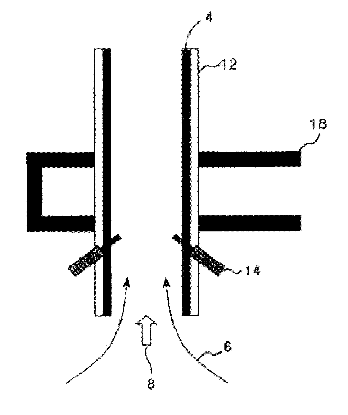
In addition, since the existing plasma ignition apparatus still remains in the dielectric tube 12 after plasma is generated, it may be easily physically damaged due to the plasma.
Thus, in order to avoid such a physical damage, additional treatments are needed for the ignition apparatus, which increases process costs.
Moreover, the dielectric tube should be precisely processed such that the metal tip may be inserted into the dielectric tube made of quartz, so the overall manufacture costs for the apparatus are increased.

Method used


Image

  • Apparatus for normal pressure plasma ignition and method for normal pressure plasma ignition using same
  • Apparatus for normal pressure plasma ignition and method for normal pressure plasma ignition using same
  • Apparatus for normal pressure plasma ignition and method for normal pressure plasma ignition using same

Examples


examples

[0059]The examples and experiments will now be described. The following examples and experiments are for illustrative purposes only and not intended to limit the scope of this disclosure.

[0060]Plasma Generation Experiment

[0061]While applying microwave of 2.45 GHz, 10 to 30 lpm of torch gas (helium) was flown to an atmospheric plasma system as shown in FIG. 3 for 5 to 10 seconds. After that, an ignition rod (tungsten) of the ignition apparatus was inserted into a reactor (into the dielectric tube).

[0062]Right after the ignition rod was inserted into the waveguide, the ignition rod was heated by means of microwave applied into the waveguide, and then thermoelectrons were emitted to generate arc. Also, after 1 to 5 seconds from the insertion of the ignition rod, plasma was generated.

[0063]Through this experimental example and pictures, it could be understood that atmospheric plasma may be effectively generated in the waveguide by means of a mechanical method, i.e. the insertion of the ...


PUM


Abstract

Provided are an apparatus for normal pressure plasma ignition and a method for normal pressure plasma ignition using the same. The apparatus for normal pressure plasma ignition of the present invention comprises a wave guide tube wherein microwaves are applied, a dielectric tube that penetrates said wave guide tube and introduces a reactant gas, and an ignition apparatus for normal pressure plasma wherein microwaves are applied in said dielectric tube to turn said reactant gas into plasma, wherein said ignition apparatus penetrates said dielectric tube and includes an ignition rod that emits thermal electrons as said microwaves are applied in said dielectric tube. The apparatus for normal pressure plasma ignition according to the present invention enables ignition to be accomplished without power, so that the problems with the prior art that requires high voltage (excessive power, stability issues) may be avoided at the same time. In addition, the normal pressure plasma ignition apparatus according to the present invention enables movement of the ignition rod inside and outside its dielectric tube so that physical damage to the ignition apparatus due to plasma heat may be prevented, and also affords the effect that the scope of metallic materials used in the ignition apparatus is significantly wider than that of the prior art.

Description

BACKGROUND[0001]1. Field[0002]This disclosure relates to an atmospheric plasma ignition apparatus and an atmospheric plasma ignition method using the same, and more particularly, to an atmospheric plasma ignition apparatus, which may make ignition in a non-electric manner, thus solving many problems caused by high voltage (e.g., excessive electric power and safety-related problem), preventing the ignition apparatus from being physically damaged due to plasma heat, and allowing to use more kinds of metal materials for the ignition apparatus than existing cases, and an atmospheric plasma ignition method using the same.[0003]2. Description of the Related Art[0004]If heat is continuously applied to a gaseous material to increase its temperature, an aggregate of particles, each having nucleus and electron, are made. This aggregate is called the fourth phase along with solid, liquid and gas, and the material in this phase is called plasma.[0005]In modern industries, plasma is used in vari...

Claims


Application Information

Patent Timeline
Patent Type & Authority Applications(United States)
IPC IPC(8): H05H1/46
CPCH05H1/24H05H1/46H05H2240/10H05H1/4622H05H1/30
Inventor KIM, IK NYEONJI, YOUNG YEON
Owner TRIPLECORESKOREA
Learn More