
Hardened Martensitic Steel Having a Low Cobalt Content, Process for Manufacturing a Part from Steel, and Part thus Obtained

Active Publication Date: 2011-09-22
AUBERT & DUVAL FR
View PDF5 Cites 9 Cited by
  • Summary
  • Abstract
  • Description
  • Claims
  • Application Information

AI Technical Summary

Benefits of technology

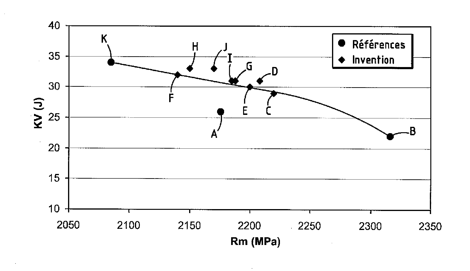
[0014]An object of the invention is to provide a steel which may notably be used for manufacturing mechanical parts such as transmission shafts, or structural members, having higher resilience while having a significant mechanical strength. This steel should also have a lower manufacturing cost than the most performing steels presently known for these uses, in particular by a significantly more reduced cobalt content.

Problems solved by technology

The requirement of excellent hot mechanical strength in certain applications prevents the use of carbon steels or so-called “weakly alloyed” steels, the strength of which starts to degrade from 200° C. Further, the toughness of these steels is generally no longer satisfactory when they are treated for mechanical strength levels of more than 2,000 MPa, and, generally, their “true” yield strength is much smaller than their maximum strength measured in the tensile test: the yield strength is therefore a dimensioning criterion which becomes a penalty in this case.
But these maraging steels quite systematically contain high nickel, cobalt and molybdenum contents, all elements which are costly and subject to notable variations of their quotation on the commodity market.
They also contain titanium, used for its strong contribution to secondary hardening, but which is mainly involved in the lowering of the fatigue strength of maraging steels due to the nitride TiN, the formation of which is quasi impossible to avoid during the smelting of steels even containing only a few tenths of percents.
This composition has the drawback of requiring a high Co content (8 to 16%), which makes the steel very expensive (N.B.: in the present text, all the contents of the different elements are expressed in weight %).
However, this steel always contains relatively large amounts of cobalt.
With the steels as proposed in WO-A-20061114499 and U.S. Pat. No. 5,393,488, it is possible to obtain good resilience but for certain applications the latter may prove to be insufficient.

Method used


Image

  • Hardened Martensitic Steel Having a Low Cobalt Content, Process for Manufacturing a Part from Steel, and Part thus Obtained

Examples


Embodiment Construction

[0070]In the steels of the class of those of the invention, “duplex” hardening is carried out, i.e. obtained together by intermetallic compounds of the β-NiAl type and by carbides of the M2C type, in the presence of reversion austenite formed / stabilized by nickel enrichment obtained by diffusion during age hardening, which gives ductility to the structure by the formation of a sandwich structure (a few % of stable and ductile austenite between the laths of hardened martensite).

[0071]The formation of nitrides, of Ti, Zr and Al notably, should be avoided, which are embrittling: they deteriorate the toughness and fatigue strength. As these nitrides may precipitate from contents of 1 to a few ppm of N in the presence of Ti, Zr and / or Al and as conventional smelting means make it difficult to attain less than 5 ppm of N, the steel of the invention observes the following rules.

[0072]In principle, any addition of Ti is limited (maximum allowed: 100 ppm), and N is limited as far as possible...


PUM

PropertyMeasurementUnit
Temperatureaaaaaaaaaa

Abstract

A steel characterized in that its composition is percentages by weight:C=0.18-0.30%Co=1.5-4%Cr=2-5%Al=1-2%Mo+W / 2=1-4%V=traces-0.3%Nb=traces-0.1%B=traces-30 ppmNi=11-16% where Ni≧7+3.5 AlSi=traces-1.0%Mn=traces-4.0%Ca=traces-20 ppmRare earths=traces-100 ppmif N≦10 ppm, Ti+Zr / 2=traces-100 ppm where Ti+Zr / 2≦10 Nif 10 ppm<N≦20 ppm, Ti+Zr / 2=traces-150 ppmO=traces-50 ppmN=traces-20 ppmS=traces-20 ppmCu=traces-1%P=traces-200 ppmthe remainder being iron and inevitable impurities resulting from the smelting. A process for manufacturing a part from this steel, and part thus obtained.

Description

[0001]The invention relates to martensitic steel hardened by a duplex system, i.e. by precipitation of intermetallic compounds and of carbides obtained by means of suitable composition of the steel and suitable heat ageing treatment.BACKGROUND[0002]This type of steel provides:[0003]very high mechanical strength, but at the same time high toughness and ductility, in other words low sensitivity to brittle failure; this very high strength subsists under hot conditions up to temperatures of the order of 400° C.;[0004]good fatigue properties, which notably implies the absence of harmful inclusions such as nitrides and oxides; this characteristic has to be obtained by a suitable composition and careful conditions for elaborating the liquid metal.[0005]Further, it is carburizable and nitridable, so as to be able to harden its surface in order to give it good resistance to abrasion and lubricated friction.[0006]Conceivable applications of this steel concern all fields of mechanics where str...

Claims


Application Information

Patent Timeline
IPC IPC(8): C21D8/00C21D6/04C23C22/00C22C38/60C22C38/00C22C38/42C22C38/30
CPCC21D1/32C22C38/54C21D6/007C21D6/04C21D9/0068C21D9/28C21D2211/008C22C38/001C22C38/005C22C38/02C22C38/04C22C38/06C22C38/42C22C38/44C22C38/46C22C38/48C22C38/52C21D6/004
Inventor ROCH, FRANCOIS
Owner AUBERT & DUVAL FR
Learn More