
Return carbon dioxide to flashed geothermal brine to control scale deposition in a geothermal power plant

a geothermal power plant and carbon dioxide technology, applied in the direction of machines/engines, mechanical equipment, separation processes, etc., can solve the problems of high heat transfer performance of the binary heat exchanger, damage to the reinjection well, and degrade the heat transfer performance, so as to reduce the ph of the brine and reduce the supersaturation of ph sensitive minerals

Active Publication Date: 2011-09-15
CHEMTREAT
View PDF8 Cites 8 Cited by
  • Summary
  • Abstract
  • Description
  • Claims
  • Application Information

AI Technical Summary

Benefits of technology

[0015]The evolution of vapor from the brine that occurs when pressure drops below the bubble point quickly strips dissolved gases from the brine. The first portion of vapor that evolves from the brine contains a large concentration of CO2 and a substantial fraction of the CO2 initially dissolved in the brine. If physically separated from the brine before the brine goes to the main stages of steam separation (which provide steam to the turbine), this first portion of vapor or gas-rich steam provides a source of CO2 in relatively concentrated form essentially at no cost.
[0018]In this way, the binary heat exchanger and injection wells of a steam-binary hybrid geothermal power plant can be protected from the detrimental effects of precipitation and scale deposition without the expense and bother of providing chemicals from without. Also, atmospheric emissions of CO2, hydrogen sulfide and other gases are decreased, because the gases contained in the gas-rich vapor returned to the brine are reinjected into the geothermal reservoir together with the brine.

Problems solved by technology

However, the binary heat exchanger is highly sensitive to scale deposition and precipitation of solids.
Scale deposited on the water side of the heat exchange surfaces seriously degrades heat transfer performance and increases the pressure drop of brine flowing through the binary heat exchanger, while solids precipitated from the brine tend to accumulate at the tube sheets, plugging the tubes.
Continuing precipitation of solids can also damage the reinjection wells by accumulating in the wellbore or cementing the cracks and pores in the reservoir rock, reducing permeability.
Silicate inhibitors are expensive, and using them dramatically increases operating costs.
This problem of high treatment cost has been recognized from the time that steam-binary hybrid geothermal power plants were first operated some twenty years ago, but remains unsolved.
More typical geothermal brines, which contains five percent or less dissolved salts, generally have higher alkalinity than the hypersaline brines, and the amount of acid needed to decrease pH by an effective amount is prohibitive.
In either case, decreasing pH increases the corrosivity of the brine.
If acid in excess of the alkalinity is added to the brine, pH drops precipitously, and severe corrosion results.
Because oxygen is present in the NCGs, combining NCGs with the brine would make it highly corrosive.

Method used


Image

  • Return carbon dioxide to flashed geothermal brine to control scale deposition in a geothermal power plant
  • Return carbon dioxide to flashed geothermal brine to control scale deposition in a geothermal power plant
  • Return carbon dioxide to flashed geothermal brine to control scale deposition in a geothermal power plant

Examples


case 1

P(HX) and X(CO2,40) is large

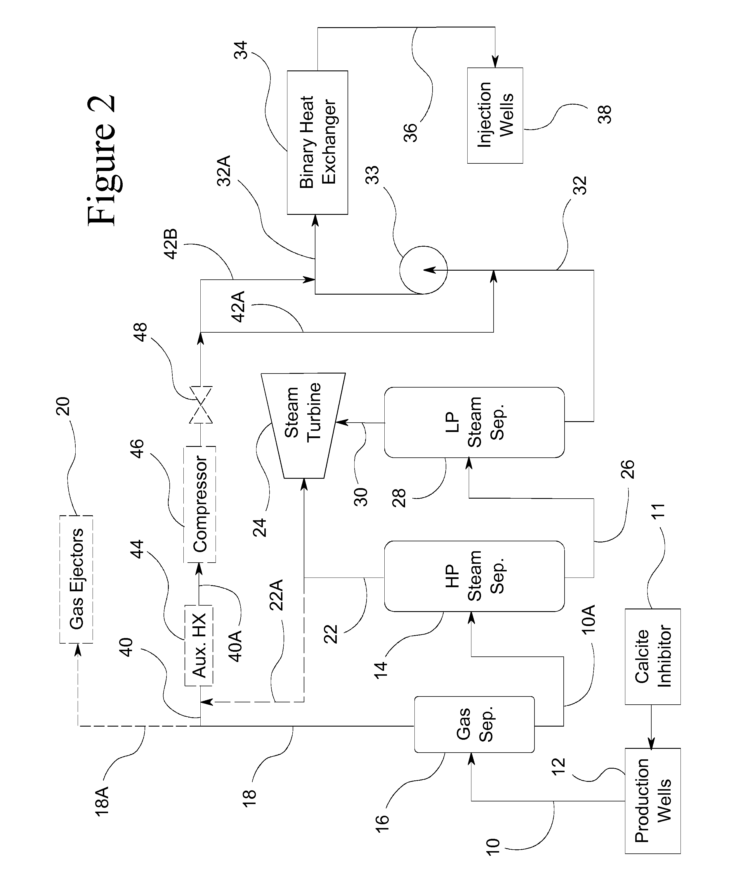
[0062]In this case, compressor 46 is not needed, and gas-rich vapor 40 is preferably combined with flashed brine 32 downstream of pump 33; that is, following path 42B. If X(CO2,40) is fairly large (for example, above 10 mole-%), the amount of water vapor in gas-rich vapor 40 will be modest, and auxiliary heat exchanger 44 would be of little benefit. Alternatively, if X(CO2,40) is large and pump 32 has sufficient suction head, gas-rich vapor 40 can be combined with brine 32 upstream of pump 33 following path 42A. Pump suction must be considered in this case, because the water vapor added to brine 32 with gas-rich vapor 40 will increase the temperature and vapor pressure of the brine, possibly causing cavitation and reducing the efficiency of pump 33 if suction head is insufficient.

case 2

P(HX) and X(CO2,40 or 22A) is small

[0063]In this case path 42B can be used, and auxiliary heat exchanger 44 can optionally be used to condense most of the water vapor in gas-rich vapor 40 or high pressure steam 22A. Gas-rich vapor 40 or high pressure steam 22A can also be combined with brine 32 upstream of pump 33 following path 42A; in this case auxiliary heat exchanger 46 should be used to prevent boiling and cavitation at the suction of pump 33.

case 3

P(HX) and X(CO2,40) is large

[0064]In this case gas-rich vapor 40 can be combined with brine 32 upstream of pump 33 following path 42A if sufficient suction head is available. Optionally, gas-rich vapor 40 can be combined with brine 32 downstream of pump 33 following path 42B if compressor 46 is used. Auxiliary heat exchanger 44 is desirable in this case to minimize the amount of water vapor that enters compressor 46.


PUM

PropertyMeasurementUnit
weight percentaaaaaaaaaa
temperatureaaaaaaaaaa
alkalinityaaaaaaaaaa

Abstract

Geothermal brine always contains some carbon dioxide in solution. Separating steam from geothermal brine removes the carbon dioxide, sharply increasing the pH of the brine and causing precipitation of pH sensitive minerals, including calcium carbonate, magnesium silicate and other metal silicates, clays, and metal sulfides. The binary heat exchanger in a steam-binary hybrid geothermal power plant is especially sensitive to scale deposition from flashed geothermal brine, and application of expensive scale inhibitors is required.Deposition of scale in the binary heat exchanger can be controlled by separating a small amount of gas-rich vapor from the brine before the main stage of steam separation, and combining this gas rich vapor with the flashed brine before in enters the binary heat exchanger. The carbon dioxide thus added to the brine will decrease pH, decreasing or completely blocking precipitation and deposition of pH sensitive minerals as scale.

Description

RELATED PATENT APPLICATIONS[0001]Priority is claimed of Provisional Patent Application 61 / 425,154 filed 20 Dec. 2010.FIELD OF INVENTION[0002]A method and power plant improvements are provided which allow deposition of scale from flashed geothermal brine to be controlled at small cost, thereby eliminating operational problems while decreasing the need for costly treatment chemicals.BACKGROUND[0003]While in the geothermal reservoir underground, geothermal brine is in chemical equilibrium with most of the minerals present in the reservoir rock, and chemical constituents of these minerals are dissolved in the brine.[0004]When steam is separated from produced geothermal brine, the temperature drops, and pH increases. The solubility of several minerals commonly precipitating from geothermal brine or depositing as scale is highly sensitive to brine pH; these include calcite (calcium carbonate) and other carbonates, magnesium silicates, calcium silicates, clay minerals, and the sulfides of ...

Claims


Application Information

Patent Timeline
Patent Type & Authority Applications(United States)
IPC IPC(8): F01K27/00F03G7/04C02F5/00
CPCB01D19/0036C02F5/00Y02E10/10F03G7/04F01K7/06
Inventor WERES, OLEH
Owner CHEMTREAT
Learn More