
Compressed nanofiber composite media

a composite media and nanofiber technology, applied in the field of filter media, can solve the problems of engine damage, engine injector damage, engine flame-out,

Inactive Publication Date: 2011-09-01
CLARCOR INC
View PDF41 Cites 23 Cited by
  • Summary
  • Abstract
  • Description
  • Claims
  • Application Information

AI Technical Summary

Benefits of technology

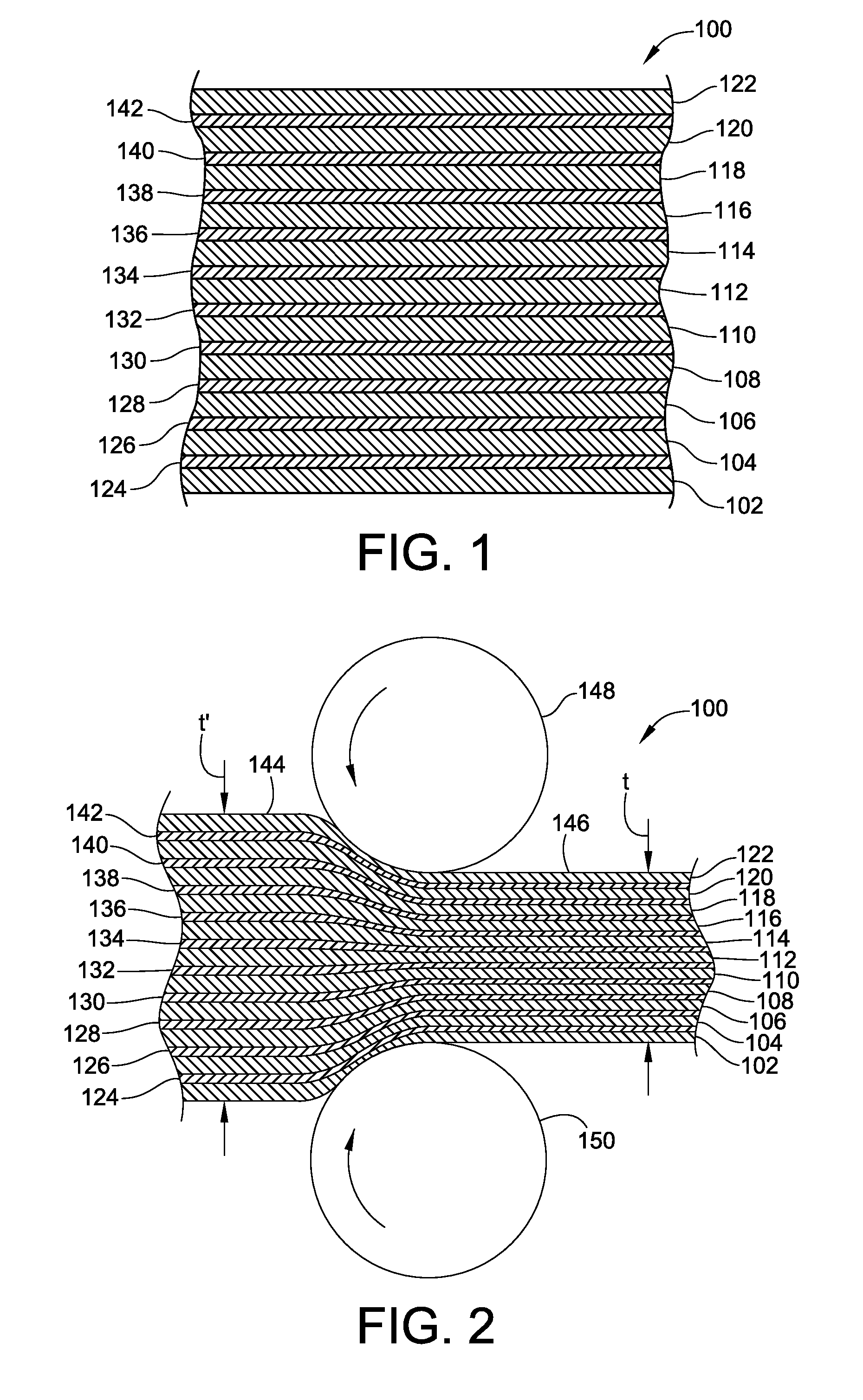
[0007]A compressed nanofiber composite filter media according to various embodiments of the present invention includes at least one substrate and fine fibers carried thereby. Preferably, the compressed filter media includes multiple substrate layers, each of which carrying fine fibers. The multiple substrate and fine fiber layers are compressed together to form the compressed composite filter media. The compressed filter media according to various embodiments of the present invention is particularly well suited for a coalescing media to coalesce water in various hydrocarbon fuels. However, the compressed filter media can also be used in other filtration applications. For example, the compressed filter media can make a very efficient water filter element.
[0008]Preferably, the substrate layers employed are relative open materials with coarse fibers to provide support while at the same time not being overly restrictive to fluid flow especially as layers are stacked and / or compressed. This structure spaces nano-fibers apart and affords the ability to provide for a much heavier total coverage of nano-fibers per square unit of area while at the same time not being overly restrictive. Further, a relatively thin substrate may be used (and compression used), such that the fine fibers throughout the media is spaced relatively close and close enough to facilitate coalescing; and thickness of the media as a whole is suitable for coalescing filtration applications and filter element arrangement. Many embodiments also employ hydrophilic fine fibers that attract as opposed to repelling water. By using multiple layers of fine fibers at sufficient coverage, water molecules or fine droplets grow within this structure and are effectively coalesced out of a fluid stream.
[0009]The multiple substrate layers and the fine fibers may and preferably are compressed together to form a coalescing filter media. As such, the coalescing filter media is compacted and high in solidity and includes a sufficient fine fiber coverage to provide a sufficient fiber surface area to coalesce emulsified water in a hydrocarbon fuel stream. The fine fibers are preferably electrospun nanofibers formed of a hydrophilic material, such as polyamide-6. The hydrophilic fine fibers further facilitate formation and growth of water droplets.
[0020]In another embodiment of the present invention, a coalescing filter media is provided. The coalescing filter media includes at least one substrate containing coarse fibers having an average fiber diameter of greater than 1 micron, and fine fibers carried by the substrate. The fine fibers are hydrophilic fibers having an average fiber diameter of less than 1 micron and provide a sufficient fiber surface area to coalesce emulsified water in a hydrocarbon fuel. In such embodiment, the hydrophilic fibers facilitate formation and growth of water droplets. The coalescing filter media can further include a drainage layer arranged on a downstream surface of the coalescing filter media. Such drainage layer can facilitate growth of the water droplet size. In one embodiment, the drainage layer is formed of a cellulous material or a fiber glass material.

Problems solved by technology

Undissolved water can be harmful to engines.
Diesel engine injectors may be damaged by steam formation, jet turbine engines may flame-out, and gasoline engines may suffer ignition problems.
The presence of wetting agents or surfactants may interfere with the coalescence of water emulsions, especially in diesel fuel or jet fuel.

Method used


Image

  • Compressed nanofiber composite media
  • Compressed nanofiber composite media
  • Compressed nanofiber composite media

Examples


Embodiment Construction

[0049]Prior to turning to the details, some lexicography will be developed to assist in understanding the present invention. As used herein, the term “substrate” is meant to be broad in nature and meant to include any structure upon which fine fibers are carried or deposited. “Substrate” may include conventional formed filter medias such as scrims and the like that may be unwound from media rolls. Such filter medias have a fiber entanglement that typically bonded or secured together mechanically, chemically, adhesively and / or otherwise and thereby have strength such that they cannot be easily torn manually (e.g. a 1 square foot sheet typically holds up to application of tension of 5 lbs force) and have filtrations properties. “Substrate” may also include looser fiber entanglements that may not be bonded together or secured together (e.g. a 1 square foot sheet may fall apart upon application of tension of 5 lbs force). A “scrim” used as herein refers to woven or non-woven fiber entan...


PUM

PropertyMeasurementUnit
diameteraaaaaaaaaa
diameteraaaaaaaaaa
diameteraaaaaaaaaa

Abstract

A coalescing media includes a compressed composite filter media comprising substrate layers and hydrophilic fine fiber layers for separating free water emulsified in fuels.

Description

CROSS-REFERENCE TO RELATED PATENT APPLICATIONS[0001]This patent application claims the benefit of U.S. Provisional Patent Application No. 61 / 330,462 filed May 3, 2010; and U.S. Provisional Patent Application No. 61 / 308,488 filed Feb. 26, 2010; and U.S. Provisional Patent Application No. 61 / 383,487 filed Sep. 16, 2010; and U.S. Provisional Patent Application No. 61 / 383,569 filed Sep. 16, 2010, the entire teachings and disclosure of which are incorporated herein by reference thereto.FIELD OF THE INVENTION[0002]This invention generally relates to a filter media, and in particular to a compressed composite media comprising a substrate and fine fibers, and method of making the same.BACKGROUND OF THE INVENTION[0003]Hydrocarbon fuels, such as diesel fuel, jet fuel, and gasoline, can entrain small amount of water. The water may be introduced in the hydrocarbon fuels, for example, by leakage, accidental contamination, or atmospheric condensation. The hydrocarbon fuels can dissolve about 75 t...

Claims


Application Information

Patent Timeline
Patent Type & Authority Applications(United States)
IPC IPC(8): B01D39/14B01D39/18
CPCB01D2239/025B01D2239/064B01D2239/0695B01D2239/0668B82Y30/00B01D39/1623B01D2239/0631B01D2239/1233B01D39/02B01D69/04B01D69/10B01D69/12
Inventor LI, LEIGREEN, THOMAS B.
Owner CLARCOR INC
Learn More