Eureka AIR delivers breakthrough ideas for toughest innovation challenges, trusted by R&D personnel around the world.

Integrated Hydromethanation Fuel Cell Power Generation

a fuel cell and hydromethane technology, applied in the direction of combustible gas catalytic treatment, combustible gas production, electrochemical generators, etc., can solve the problems of high fuel value, inefficient use, and inefficient utilization of generated hea

Active Publication Date: 2011-08-25
SURE CHAMPION INVESTMENT LTD
View PDF102 Cites 99 Cited by
  • Summary
  • Abstract
  • Description
  • Claims
  • Application Information

AI Technical Summary

Benefits of technology

"The patent describes a process for generating electrical power from non-gaseous carbonaceous materials using a hydromethanation reaction. The process involves introducing a carbonaceous feedstock, a hydromethanation catalyst, and a superheated hydromethanation gas feed stream into a hydromethanation reactor. The reactor produces a methane-enriched raw product, which is then sent to a fuel cell. The fuel cell reacts the methane with oxygen to produce electrical power and heat energy. The process is useful for generating electrical power from various non-gaseous carbonaceous materials without direct combustion. The invention also provides an apparatus for generating electrical power from non-gaseous carbonaceous materials."

Problems solved by technology

One issue with such fuel cells is that the oxidative reactions are highly exothermic, and the ability (or inability) to efficiently utilize this generated heat is directly related to the overall efficiency of the fuel cell process.
One problem with the use of methane / hydrogen co-feed streams is that a higher fuel value off gas may be produced (containing significant amounts of methane, hydrogen and carbon monoxide).
This off gas may be combusted for heat value (for example, to generate steam and electricity), but this is a relatively inefficient use.
A suitable feed stream for the fuel cell can be generated through the mixing of separately-generated hydrogen and methane streams, but this is not efficient.
The proposed configurations in the publication, however, require significant quantities of gaseous oxygen, which is provided via conventional air separation technologies that are highly inefficient and can result in a significant drag on the overall process efficiency.

Method used


Image

  • Integrated Hydromethanation Fuel Cell Power Generation
  • Integrated Hydromethanation Fuel Cell Power Generation
  • Integrated Hydromethanation Fuel Cell Power Generation

Examples


examples of specific embodiments

[0255]A specific embodiment of the process is one in which the process is a continuous process, in which steps (a), (b), (c), (d), (e), (f), (g), (h), (i), (j) and, when present, (k) are operated in a continuous manner.

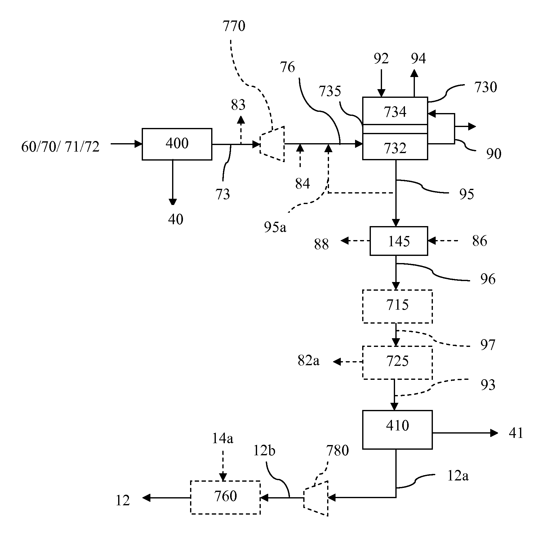
[0256]In another specific embodiment, step (k) is present. In a more specific embodiment, in step (k) at least a portion of the carbon dioxide-depleted anode exhaust stream is passed through a methane reformer unit to generate hydrogen and carbon monoxide from methane in the carbon dioxide-depleted anode exhaust stream. Additionally, in another embodiment, the methane reformer unit utilizes non-catalytic partial oxidation process or an autothermal reforming process, and wherein an oxygen-rich gas stream is fed into the methane reformer unit along with the carbon dioxide-depleted anode exhaust stream.

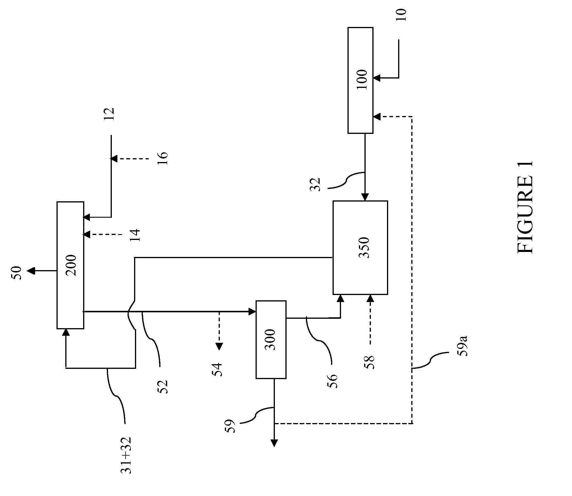
[0257]Another specific embodiment is one in which oxygen-rich gas stream (14) is supplied periodically or continuously to hydromethanation reactor (200), and the amount of...


PUM

PropertyMeasurementUnit
electrical poweraaaaaaaaaa
heat energyaaaaaaaaaa
temperatureaaaaaaaaaa

Abstract

The present invention relates to processes and apparatuses for generating electrical power from certain non-gaseous carbonaceous feedstocks through the integration of catalytic hydromethanation technology with fuel cell technology.

Description

CROSS REFERENCE TO RELATED APPLICATION[0001]This application claims priority under 35 U.S.C. §119 from U.S. Provisional Application Ser. No. 61 / 307,226 (filed 23 Feb. 2010), the disclosure of which is incorporated by reference herein for all purposes as if fully set forth.FIELD OF THE INVENTION[0002]The present invention relates to processes and apparatuses for generating electrical power from certain non-gaseous carbonaceous feedstocks through the integration of catalytic hydromethanation technology with fuel cell technology.BACKGROUND OF THE INVENTION[0003]Fuel cells are receiving considerable attention due to their direct and potentially highly-efficient generation of electrical power through the electrochemical conversion of hydrogen and other fuel sources without direct combustion.[0004]In a typical fuel cell, an oxygen-containing gas (such as air) enters the fuel cell on the cathode side of the cell. At the cathode, oxygen in the air is converted (reduced) to oxide ions, which...

Claims


Application Information

Patent Timeline
Patent Type & Authority Applications(United States)
IPC IPC(8): H01M8/06
CPCC01B3/323Y02E60/324C01B2203/0283C01B2203/0415C01B2203/042C01B2203/0465C01B2203/0485C01B2203/066C01B2203/0805C10L3/10C10L3/102H01M8/0618H01M8/0643H01M8/0668H01M8/0675H01M2008/1293Y02E20/18Y02E60/50C10J3/463C10K3/04C10J2300/0916C10J2300/093C10J2300/0943C10J2300/0986C10J2300/1646C10J2300/1662C10J2300/1671C10J2300/1823C10J2300/1884C10K1/004C10K1/005C10J2300/0906C10J2300/0976C10J2300/1628Y02E60/525C01B2203/025Y02E60/32
Inventor POWELL, CHARLES ALLENRAMAN, PATTABHI K.ROBINSON, EARL T.SIRDESHPANDE, AVINASH
Owner SURE CHAMPION INVESTMENT LTD
Why Eureka
Eureka Blog
Learn More