Eureka AIR delivers breakthrough ideas for toughest innovation challenges, trusted by R&D personnel around the world.

Fixing device and image forming apparatus incorporating same

a technology of fixing device and image forming apparatus, which is applied in the direction of electrographic process apparatus, instruments, optics, etc., can solve the problems of limiting the application of the technology to relatively slow imaging systems, the vulnerability of wear and tear of the fixing device using a thin film fuser, and the drawbacks of the thin film fuser

Inactive Publication Date: 2011-08-25
RICOH KK
View PDF29 Cites 118 Cited by
  • Summary
  • Abstract
  • Description
  • Claims
  • Application Information

AI Technical Summary

Benefits of technology

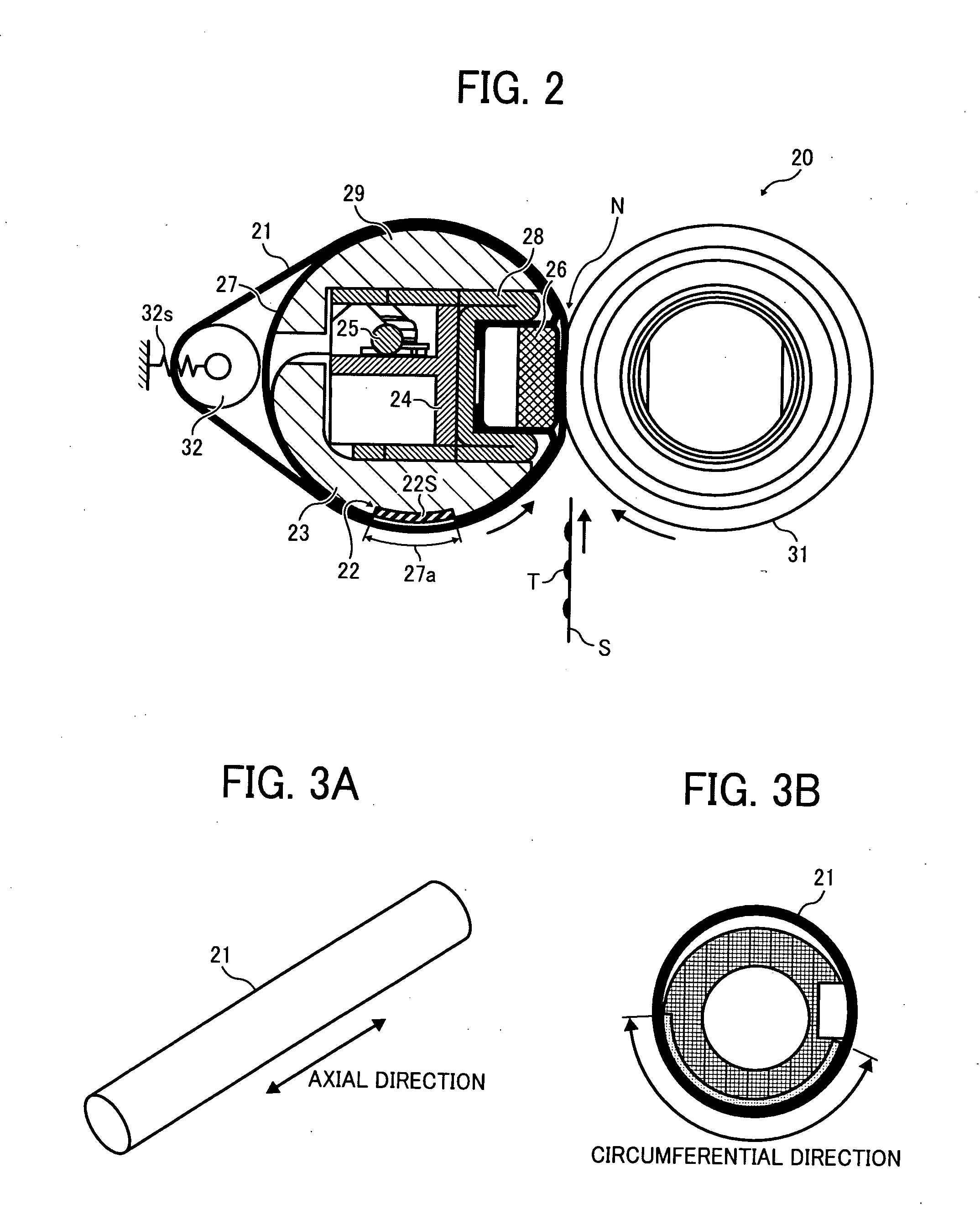
The present invention provides a novel fixing device for fixing toner images on a recording medium. The device includes an endless fuser belt, a contact member, a pressure member, a heater, a heater support, and a belt tensioner. The fuser belt is looped into a cylindrical configuration and rotated. The contact member is inside the fuser belt and extends in the axial direction. The pressure member is pressed against the contact member through the fuser belt to form a fixing nip. The heater is disposed inside the fuser belt to heat it. The heater support holds the heater in position. The belt tensioner is inside the fuser belt to tighten it so as to maintain it in contact or close proximity with the heater. The invention also provides a novel image forming apparatus including the fixing device.

Problems solved by technology

By contrast, the multi-roller belt fuser, although advantaged over a conventional roller-based fuser, involves a substantial warm-up time to heat the fixing nip to a temperature sufficient for fusing toner and first-print time to complete an initial print job upon activation, limiting its application to relatively slow imaging systems.
Although generally successful for its intended purpose, the fixing device using a thin film fuser also has drawbacks.
One drawback is its vulnerability to wear, where the heat-resistant film has its inner surface repeatedly brought into frictional contact with the surface of the stationary ceramic heater.
The frictionally contacting surfaces of the film and the heater readily chafe and abrade each other, which, after a long period of operation, results in increased frictional resistance at the heater / film interface, leading to disturbed rotation of the fuser belt, or increased torque required to drive the pressure roller.
If not corrected, such defects can eventually cause failures, such as displacement of a printed image caused by a recording sheet slipping through the fixing nip, and damage to a gear train driving the fixing members due to increased stress during rotation.
Another drawback is the difficulty in maintaining a uniform processing temperature throughout the fixing nip.
The problem arises where the fuser film, which is once locally heated at the fixing nip by the heater, gradually loses heat as it travels downstream from the fixing nip, so as to cause a discrepancy in temperature between immediately downstream from the fixing nip (where the fuser belt is hottest) and immediately upstream from the fixing nip (where the fuser belt is coldest).
Such thermal instability adversely affects fusing performance of the fixing device, particularly in high-speed applications where the rotational fixing member tends to dissipate higher amounts of heat during rotation at a high processing speed.
According to this arrangement, provision of the lubricant sheet prevents abrasion and chafing at the interface of the stationary and rotatable fixing members, as well as concomitant defects and failures of the fixing device.
However, the conventional method does not address the thermal instability caused by locally heating the fixing belt at the fixing nip, as is the case with the conventional fixing device.
Further, this method involves a fixing roller that exhibits a relatively high heat capacity and therefore takes time to heat up to a desired processing temperature, leading to a longer warm-up time.
Hence, although designed to provide an increased thermal efficiency through use of an elastically deformable fuser roller, the conventional method fail to provide satisfactory fixing performance for high-speed, on-demand applications.
One drawback encountered when using a tubular belt holder to heat a fuser belt is the difficulty in maintaining uniform spacing between the fuser belt and the belt holder.
That is, the elastic fuser belt during rotation occasionally moves too far from the surface of the belt holder to conduct appropriate amounts of heat from the belt holder to the fuser belt.
The lack of conduction can cause the metal-based belt holder to locally overheat and burn, resulting in an increased torque of the fuser belt rotating along the damaged surface.
One drawback of this method is that the flexible fuser belt suffers from variations in temperature as it occasionally contacts or moves away from the surface of the resistive heater, as is the case with the one entrained around the tubular belt holder described above.
In particular, the fuser belt can locally overheat where the fuser belt, disposed in close proximity with the resistive heater for obtaining high thermal efficiency, contacts the heater to conduct excessive amounts of heat therebetween.
Such localized heating of the fuser belt results in poor imaging performance due to non-uniform distribution of heat across the fixing nip.
Another drawback is that the resistive heater can wear and break as it undergoes repeated flexion or stress caused by rotational vibration transmitted from the pressure roller through the fuser belt.
Once broken, the metal-based resistive heater no longer gives off sufficient heat to the fuser belt, resulting in defective fusing performance of the fixing device.

Method used


Image

  • Fixing device and image forming apparatus incorporating same
  • Fixing device and image forming apparatus incorporating same
  • Fixing device and image forming apparatus incorporating same

Examples


Embodiment Construction

[0046]In describing exemplary embodiments illustrated in the drawings, specific terminology is employed for the sake of clarity. However, the disclosure of this patent specification is not intended to be limited to the specific terminology so selected, and it is to be understood that each specific element includes all technical equivalents that operate in a similar manner and achieve a similar result.

[0047]Referring now to the drawings, wherein like reference numerals designate identical or corresponding parts throughout the several views, exemplary embodiments of the present patent application are described.

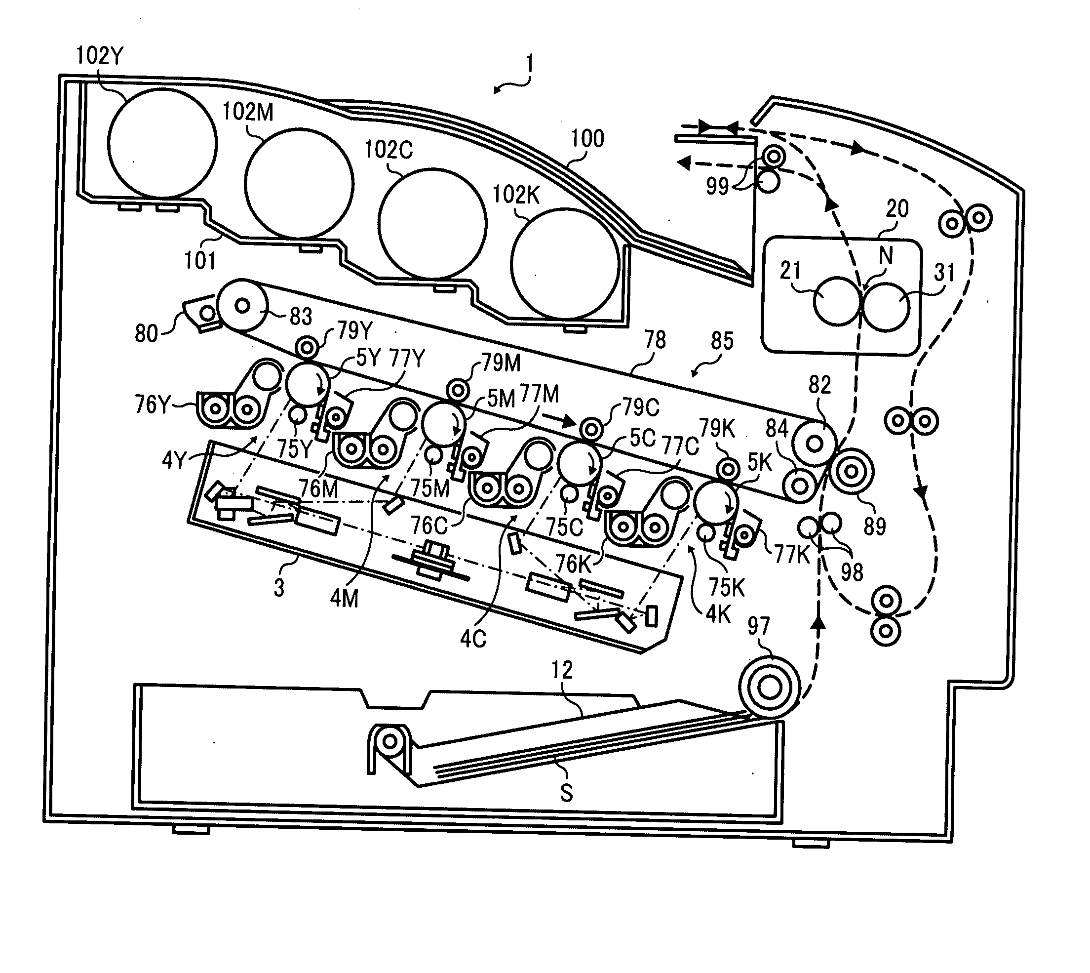
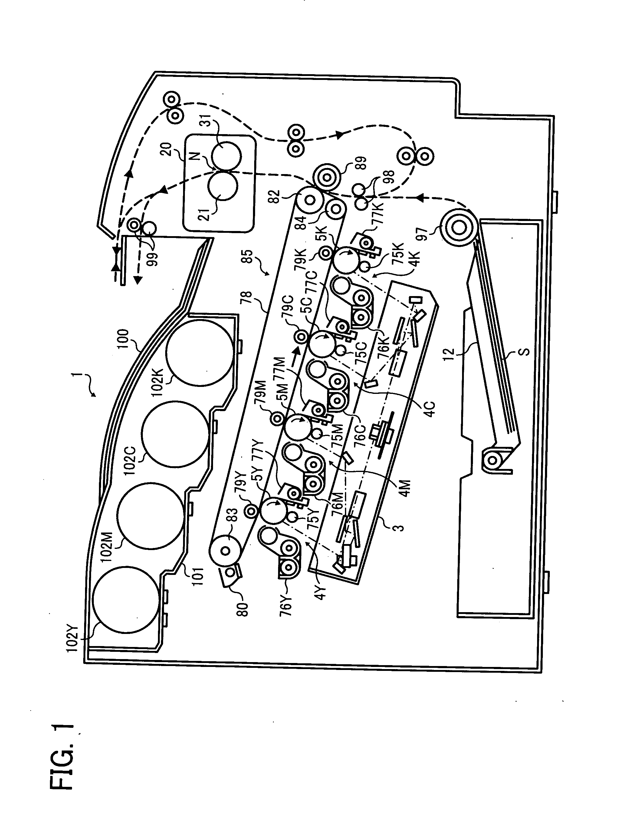
[0048]FIG. 1 schematically illustrates an image forming apparatus 1 incorporating a fixing device 20 according to one embodiment of this patent specification.

[0049]As shown in FIG. 1, the image forming apparatus 1 is a tandem color printer including four imaging stations 4Y, 4M, 4C, and 4K arranged in series along the length of an intermediate transfer unit 85 and adjacent to a ...


PUM


Abstract

A fixing device includes an endless fuser belt, a contact member, a pressure member, a heater, a heater support, and a belt tensioner. The endless fuser belt is looped into a generally cylindrical configuration extending in an axial direction thereof. The contact member extends in the axial direction inside the loop of the fuser belt. The pressure member extends in the axial direction with the belt interposed between the contact member and the pressure member. The pressure member is pressed against the contact member through the fuser belt to form a fixing nip. The heater is disposed inside the loop of the fuser belt to heat the fuser belt. The heater support is disposed inside the loop of the fuser belt to hold the heater in position. The belt tensioner is disposed inside the loop of the fuser belt to tighten the fuser belt.

Description

CROSS-REFERENCE TO RELATED APPLICATIONS[0001]The present patent application claims priority pursuant to 35 U.S.C. §119 from Japanese Patent Application No. 2010-040255, filed on Feb. 25, 2010, which is hereby incorporated by reference herein in its entirety.BACKGROUND OF THE INVENTION[0002]1. Field of the Invention[0003]The present invention relates to a fixing device and an image forming apparatus incorporating the same, and more particularly, to a fixing device that fixes a toner image in place on a recording medium with heat and pressure, and an electrophotographic image forming apparatus, such as a photocopier, facsimile machine, printer, plotter, or multifunctional machine incorporating several of those imaging functions, incorporating such a fixing device.[0004]2. Description of the Background Art[0005]In electrophotographic image forming apparatuses, such as photocopiers, facsimile machines, printers, plotters, or multifunctional machines incorporating several of those imagin...

Claims


Application Information

Patent Timeline
Patent Type & Authority Applications(United States)
IPC IPC(8): G03G15/20
CPCG03G15/2053G03G2215/2035G03G2215/00139
Inventor IWAYA, NAOKIYOSHIKAWA, MASAAKIISHII, KENJIYOSHINAGA, HIROSHITOKUDA, TETSUOYAMAGUCHI, YOSHIKIFUJIMOTO, IPPEIIKEBUCHI, YUTAKAIMADA, TAKAHIROHASE, TAKAMASASHIMOKAWA, TOSHIHIKO
Owner RICOH KK
Why Eureka
Eureka Blog
Learn More