
Machine Tool with an Active Electrical Generator for Power Generation

a technology of power generation and electrical generator, which is applied in the direction of portable power-driven tools, manufacturing tools, metal sawing accessories, etc., can solve the problems of energy supply to light-emitting devices, and achieve the effect of saving installation space and considerable additional costs

Inactive Publication Date: 2011-08-25
ROBERT BOSCH GMBH
View PDF7 Cites 5 Cited by
  • Summary
  • Abstract
  • Description
  • Claims
  • Application Information

AI Technical Summary

Benefits of technology

This additional energy source can be designed to be independent of the mains supply, with the result that no additional elements for rectification and transformation of the mains current need to be installed in the machine. This may be advantageous in particular in the case of handheld machine tools since a weight saving can also be made. In addition, the electrical circuit of the generator according to the disclosure can be designed for operation on a low voltage (for example less than 50 V) and is therefore not subject to the requirements for mains-operated machines, such as the maintenance of insulation gaps, for example. This provides greater freedom in terms of the structural design of the machine tool.
In accordance with a further exemplary embodiment, the generator can have a second circuit which is electrically isolated from or independent of the first circuit of the machine. The first circuit is connected, for example, to a mains supply or a rechargeable battery supply. The second circuit can generate a voltage which is different from the first circuit by the operation of the generator. As a result, for example, a machine-internal light source, for example, can be supplied with energy without a mains voltage needing to be transformed and rectified. It is thus possible to dispense with additional components and therefore to save installation space and considerable additional costs.

Problems solved by technology

However, the supply of energy to the light-emitting means can pose a problem.

Method used


Image

  • Machine Tool with an Active Electrical Generator for Power Generation
  • Machine Tool with an Active Electrical Generator for Power Generation
  • Machine Tool with an Active Electrical Generator for Power Generation

Examples


Embodiment Construction

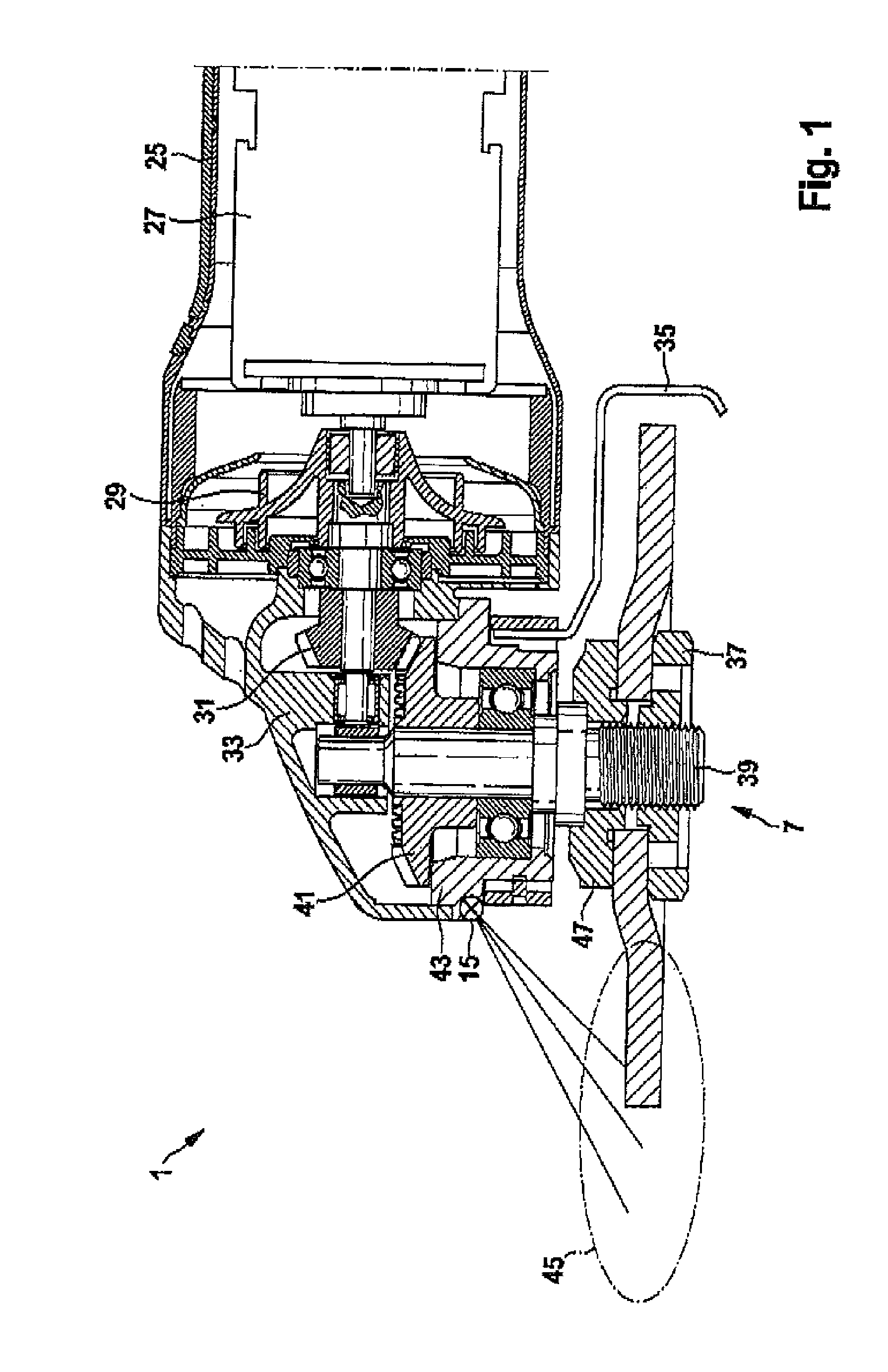
FIGS. 1 to 11 illustrate the machine tool with a rotating rotor using the exemplary embodiment of an angle grinder, and FIGS. 12 to 17 illustrate the machine tool with a linearly oscillating rotor using the example of a jigsaw. FIGS. 1 to 7 show an exemplary embodiment of the generator with axial alignment of the magnetic lines of force in the air gap, and FIGS. 8 to 17 show an exemplary embodiment of the generator with radial alignment of the magnetic lines of force in the air gap. That is to say that, using the example of the angle grinder, the air gap flux in FIGS. 1 to 7 runs parallel to the axis of rotation of the generator and perpendicular to the axis of rotation of the generator in FIGS. 8 to 12.

FIG. 1 shows a schematic illustration of a cross section through an angle grinder 1. The angle grinder has the conventional components such as motor housing 25, motor 27, fan 29, pinion 31, gear housing 33, protective cover 35, two-hole nut 37, spindle 39, ring gear 41, bearing flang...


PUM

PropertyMeasurementUnit
distanceaaaaaaaaaa
voltageaaaaaaaaaa
electrical poweraaaaaaaaaa

Abstract

A machine tool with a generator for generating electrical power is disclosed. The generator has a stator with a coil and a rotor with a magnet. The rotor is capable of moving relative to the stator. An air gap is formed between the rotor and the stator. The stator and the rotor comprise a material with a relative permeability greater than the relative permeability of air and are arranged in such a way that magnetic lines of force of the magnet are guided in a targeted manner with respect to the coil. The air gap between the stator and the rotor is configured in such a way that a large proportion of the lines of force emanating from the magnet are guided by the stator and the rotor.

Description

This application claims priority under 35 U.S.C. § 119 to German patent application no. 10 2010 002 185.7, filed Feb. 22, 2010, the disclosure of which is incorporated herein by reference in its entirety.The present disclosure relates to a machine tool with an active electrical generator for power generation.BACKGROUNDWhen working with electric tools, auxiliary means are often required for optimizing the performance of work. For example, illumination of the working area by means of light-emitting means may be useful.DE 10 2006 045 157 A1, for example, has disclosed tools in which the light-emitting means are integrated in the tool. However, the supply of energy to the light-emitting means can pose a problem.SUMMARYAn object of the present disclosure can therefore be considered that of providing an improved machine tool which enables a supply of energy to additional elements.This object can be achieved by the subject matter of the present disclosure. Advantageous embodiments of the p...

Claims


Application Information

Patent Timeline
Patent Type & Authority Applications(United States)
IPC IPC(8): H01K7/00H02K7/14
CPCH02K7/1853H02K7/1876H02K21/16H02K35/02B23D59/00B25F5/00B23Q17/2404B24B23/028B25F5/021H02K7/145B23Q5/10
Inventor SCHOEN, LUDWIGESENWEIN, FLORIAN
Owner ROBERT BOSCH GMBH
Learn More