
Manufacturing and Installation of Insulated Pipes or Elements Thereof

a technology of insulating pipes and components, which is applied in the field of manufacturing and installation of insulating pipes or elements thereof, can solve the problems of reducing insulation efficiency, reducing insulation efficiency, and reducing insulation efficiency, so as to facilitate assembly of insulating systems, reduce bulkheads and/or spacers, and simplify manufacturing and/or installation

Inactive Publication Date: 2011-08-18
CABOT CORP
View PDF17 Cites 45 Cited by
  • Summary
  • Abstract
  • Description
  • Claims
  • Application Information

AI Technical Summary

Benefits of technology

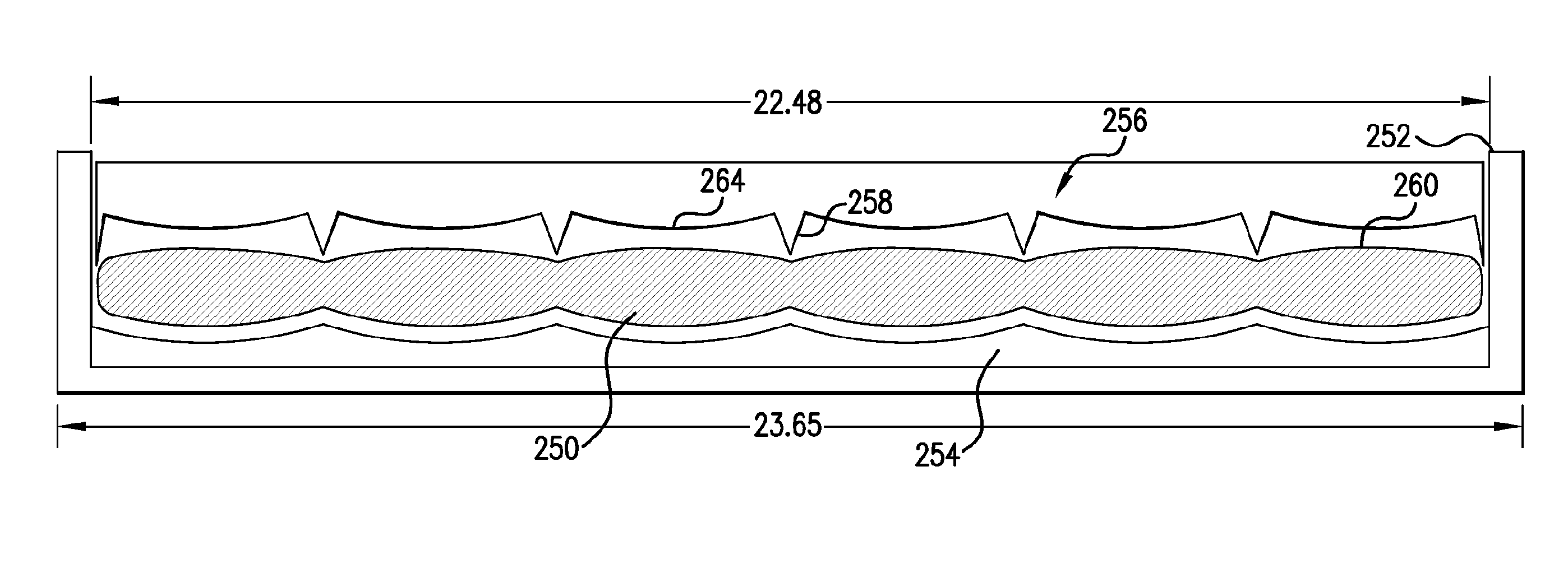
[0021]In yet another embodiment, a method for producing a container includes filling a casing with a particulate insulating material; closing the casing to form a closed container; pressing the closed container in a mold to form a shaped container; and applying a vacuum to the shaped container to reduce the pressure inside the container.
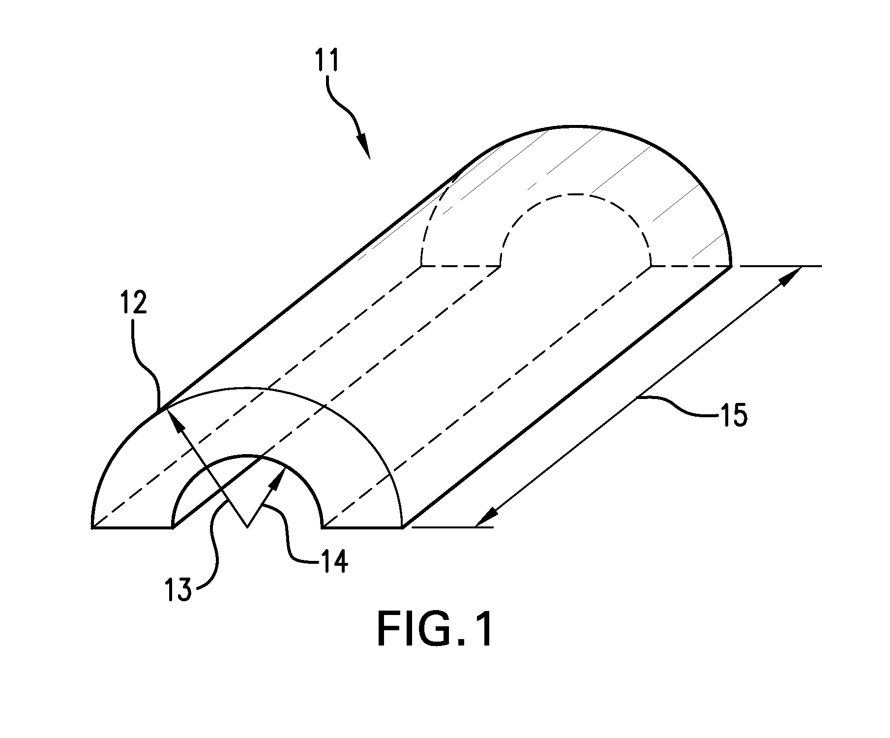
[0026]The invention can be employed to simplify manufacturing and / or installation of pipe-in-pipe arrangements. In some aspects, the use of composite aerogel material wrapped around a flow pipe can eliminate the need for an outer pipe. Techniques disclosed herein facilitate assembly of insulating systems and are particularly useful in handling and sliding heavy piping. When the insulation material itself aids in stress transfer, the pipe-in-pipe design can be thinner and / or can include fewer bulkheads and / or spacers. As bulkheads and spacers are generally made of materials that are significantly weaker insulators when compared with insulating materials such as aerogels, reducing the number and / or width of these bulkheads and spacers over the length of the system will improve thermal performance while lowering cost and complexity.
[0027]By using a mechanical rather than an adhesive bond and by their “spring back” nature, materials used can spring back to their original form even after experiencing the type of compression that would destroy adhesive bonds used in conventional polyurethane foam systems, and consequently can continue to mechanically bond the system.

Problems solved by technology

While this method can be acceptable, once excessive force breaks the adhesive bond, the value of longitudinal load transfer (and, potentially, radial load transfer) is lost.
Many existing methods of insulating pipe-in-pipe assemblies remain deficient in numerous respects.
Pre-formed insulating panels and the like, of necessity retain gaps in insulation when placed within pipe-in-pipe assemblies, both between their opposing edges and between ends when laid end-to-end, allowing for heat transfer between inner and outer pipes, which reduces insulation efficiency and requires greater amounts of insulating materials.
Maintenance of reduced pressure within the annular space of some pipe-in-pipe assemblies places great demands on forming vacuum-tight assemblies and places the performance of the assembly at risk should the vacuum be compromised.
Some insulating materials such as polyurethane foam lose insulation efficiency and / or shape over service life.
Other insulating materials require the use of a larger diameter outer pipe to accommodate sufficient insulating material due to less efficient insulation capabilities.

Method used


Image

  • Manufacturing and Installation of Insulated Pipes or Elements Thereof
  • Manufacturing and Installation of Insulated Pipes or Elements Thereof
  • Manufacturing and Installation of Insulated Pipes or Elements Thereof

Examples


first embodiment

[0238]In a first embodiment a container is altered by modifying the pressure within the container, preferably from a lower initial pressure to a higher final pressure. Equalization of the gas pressure in the container with the gas pressure in the annular space, allows compressible material within the container to expand to a greater volume.

[0239]In a specific example, a container that includes a porous, resilient, volumetrically compressible material, enclosed in a flexible gas-impermeable material, is placed inside a pressure chamber and the pressure in the chamber is reduced below atmospheric pressure. The container is sealed to be gas impermeable while the container is maintained at the reduced pressure in the chamber. The reduced pressure in the container can be any pressure that is less than atmospheric pressure. Typically, the reduced pressure is about 1 kPa or more (e.g., about 10 kPa or more, or about 20 kPa or more). Preferably, the reduced pressure is about 100 kPa or less...

second embodiment

[0245]In the invention, a container is altered to permit an increase in the volume of the compressible material and thereby form an insulated pipe-in-pipe assembly. Preferably, the compressible material is restrained is restrained at the first volume within the at least one container. That is, the container itself restrains the compressible material without or, alternatively, in addition to the action of a pressure differential between the pressure within the container and the pressure outside the container. In this regard, alteration refers to any operation that allows the compressible material to expand.

[0246]Subsequently, the container may be altered to reduce the level of restraint on the compressible material to increase the volume of the compressible material to a second volume that is greater than the first volume, thereby forming an insulated pipe-in-pipe assembly. Examples of suitable alterations include destroying the integrity of the container, transforming an inelastic c...


PUM

PropertyMeasurementUnit
Flow rateaaaaaaaaaa
Structureaaaaaaaaaa
Electrical resistanceaaaaaaaaaa

Abstract

Insulated pipe systems or assemblies include a particulate, composite or monolithic insulating aerogel material. Techniques for installing or manufacturing such systems or assemblies are described, as are components useful in the installation or manufacture processes.

Description

RELATED APPLICATIONS[0001]This application claims the benefit under 35 U.S.C. §119(e) of U.S. Provisional Patent Application No. 61 / 049,483, filed on May 1, 2008, and U.S. Provisional Application No. 61 / 152,122, filed on Feb. 12, 2009, the contents of both being incorporated herein by reference in their entirety.BACKGROUND OF THE INVENTION[0002]In deep-water hydrocarbon (e.g. oil, gas or mixtures thereof) extraction, crude oil or gas is extracted from below the sea floor and transferred via a pipeline system to the surface of the water. It is critically important to maintain the temperature of the oil or gas flowing through the pipeline, which typically is extracted at elevated temperatures (e.g., 60-300° C.), at temperatures above about 40° C. to avoid the precipitation of solid materials and hydrates which can lead to plugging of the pipeline and can interfere with production. As the water temperature at great depths is slightly above freezing temperature (e.g, about 4° C.), provi...

Claims


Application Information

Patent Timeline
IPC IPC(8): F16L9/14B21D39/08
CPCF16L59/026F16L59/027Y10T29/49826F16L59/12F16L59/143F16L59/10F16L59/024C04B38/06C04B35/14C04B38/0054C04B38/0067
Inventor KORAVOS, JASON J.DU PLESSIS, ANDRIES J.GREENFIELD, MATTHEW B.JOHNSON, AARON H.MILLER, THOMAS MICHAEL
Owner CABOT CORP
Learn More