Light emitting element driving circuit
a technology of light emitting elements and driving circuits, which is applied in the direction of static indicating devices, incandescent lamp energy saving, instruments, etc., can solve the problems of increasing system costs, ld degradation, and responsivity degradation of driving circuits, so as to improve the control accuracy of pulse width, reduce overshoot and undershoot, and reduce the effect of overshoo
- Summary
- Abstract
- Description
- Claims
- Application Information
AI Technical Summary
Benefits of technology
Problems solved by technology
Method used
Image
Examples
first embodiment
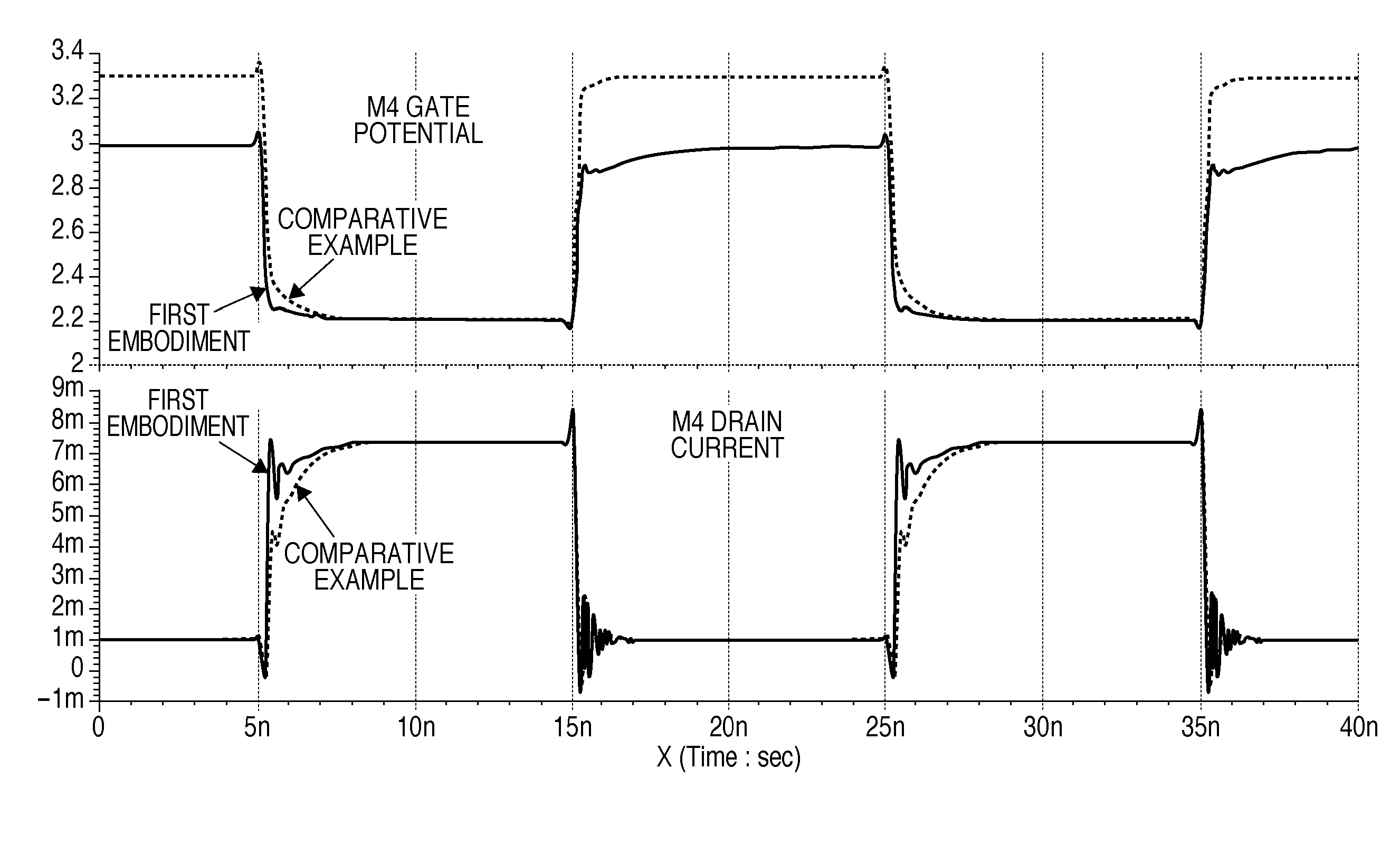
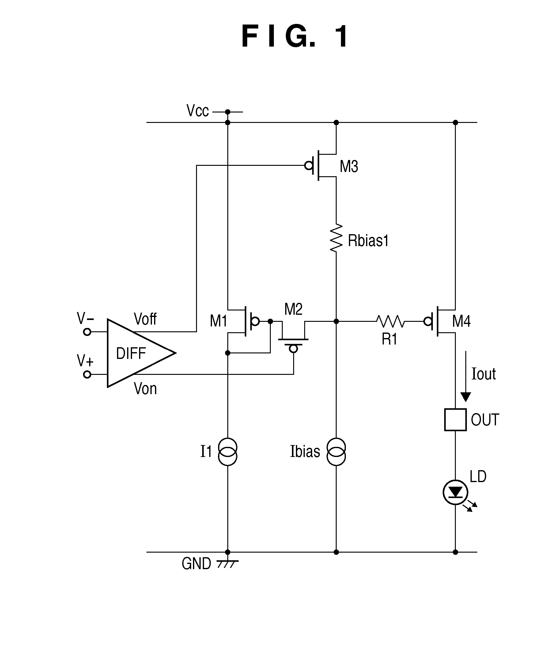
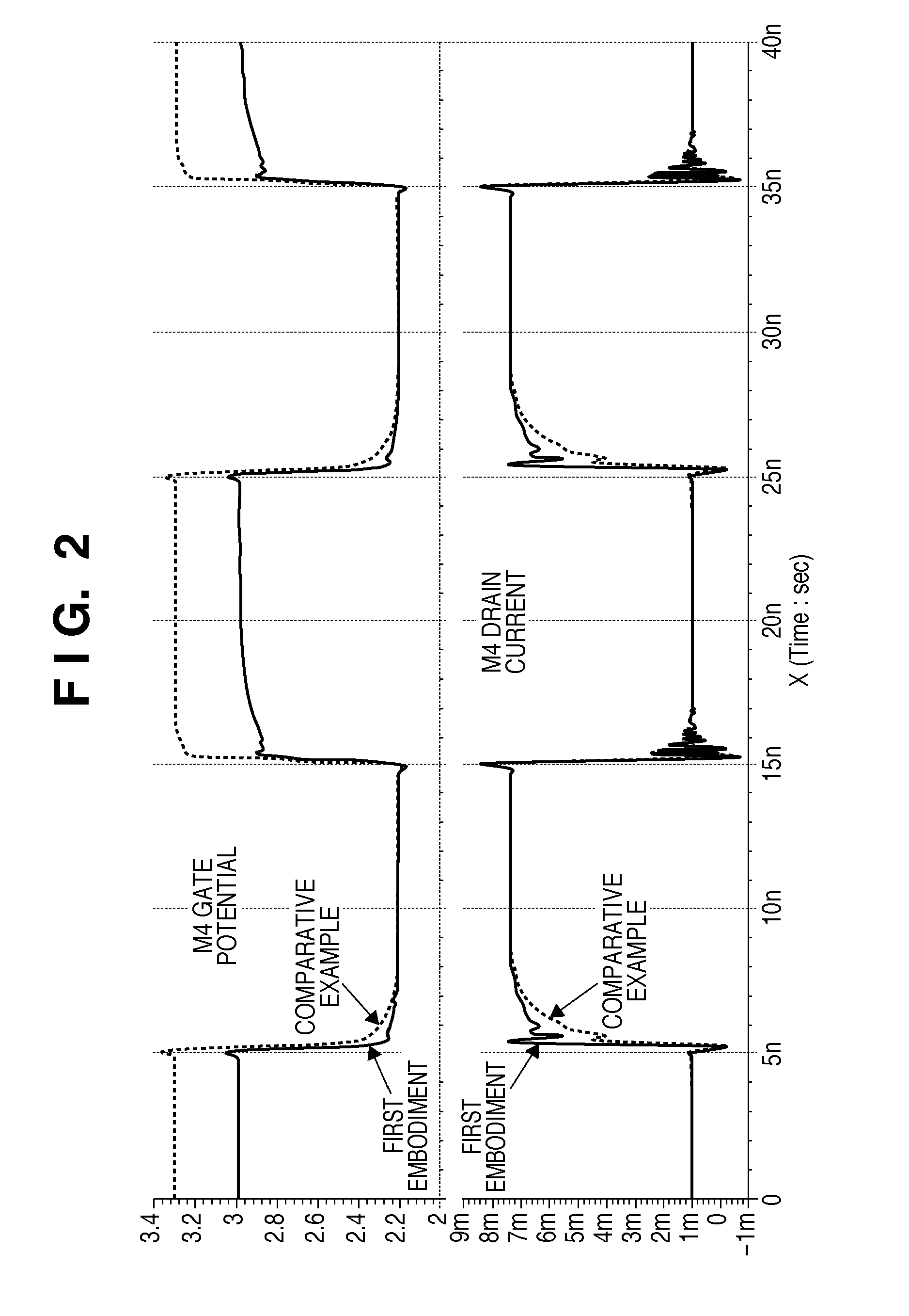
[0022]An example of a circuit arrangement according to the first embodiment will be described with reference to FIG. 1. Referring to FIG. 1, MOS transistors M1 and M4 constitute a current mirror circuit having a predetermined mirror ratio. The gate and drain of the MOS transistor M1 are connected to one terminal of a constant current source I1 whose other terminal is connected to GND (ground). The source of the MOS transistor M1 is connected to a power supply potential Vcc. The drain of a MOS transistor M2 is connected to both the gate and drain of the MOS transistor M1. The source of the MOS transistor M2 is connected to one terminal of a resistor R1 whose other terminal is connected to the gate of the MOS transistor M4. The source of the MOS transistor M2 is connected to one terminal of a resistor Rbias1 whose other terminal is connected to the drain of a MOS transistor M3. The source of the MOS transistor M2 is connected to one terminal of a constant current source Ibias whose ot...
second embodiment
[0026]An example of a circuit arrangement according to the second embodiment will be described with reference to FIG. 3. In FIG. 3, a potential to be supplied to the gate of a MOS transistor M4 is obtained by use of the following resistance circuit. This resistance circuit is formed by connecting a diode D in parallel with two serially connected resistors Rbias1 and Rbias2. The two resistors Rbias1 and Rbias2 divide the forward voltage for the diode D, which is generated by a constant current source Ibias, to obtain a potential to be supplied to the gate of a MOS transistor M4 from the connection point between the two resistors Rbias1 and Rbias2. Since other arrangements are the same as those in the first embodiment, a repetitive description of them will be omitted. In the second embodiment, the pre-bias voltage at the connection point between the two resistors Rbias1 and Rbias2 is given by Vbias=VFx{Rbias2 / (Rbias1+Rbias2)}, where VF represents the forward voltage of the diode. In t...
third embodiment
[0030]An example of a light emitting element driving circuit according to the third embodiment will be described with reference to FIG. 5. In FIG. 5, an LD is a light emitting element having current-current-to-light conversion characteristics. MOS transistors M1 and M4 constitute a current mirror circuit to operate this LD in accordance with differential data signals in a digital form.
[0031]The gate and drain of the MOS transistor M1 are connected to one terminal of a constant current source I1 whose other terminal is connected to a power supply Vcc. The source of the MOS transistor M1 is connected to GND (ground potential). MOS transistors M2 and M3 constitute a control block CTR BLOCK (control circuit) to ON / OFF-control the LD. The drain of the MOS transistor M2 is connected to both the gate and drain of the MOS transistor M1. The source of the MOS transistor M2 is connected to one terminal of a resistor R1 whose other terminal is connected to the gate of the MOS transistor M4, an...
PUM
 Abstract
Description
Claims
Application Information
 - R&D
- Intellectual Property
- Life Sciences
- Materials
- Tech Scout
- Unparalleled Data Quality
- Higher Quality Content
- 60% Fewer Hallucinations
Browse by: Latest US Patents, China's latest patents, Technical Efficacy Thesaurus, Application Domain, Technology Topic, Popular Technical Reports.
© 2025 PatSnap. All rights reserved.Legal|Privacy policy|Modern Slavery Act Transparency Statement|Sitemap|About US| Contact US: help@patsnap.com


