
Feedforward temperature control for plasma processing apparatus

a technology of plasma processing and temperature control, applied in the direction of internal feedback arrangement, process and machine control, instruments, etc., can solve the problems of poor transients with large overshoots, long settling times, and steady state errors with simple feedback control, so as to reduce steady state errors and improve response times

Active Publication Date: 2011-08-04
APPLIED MATERIALS INC
View PDF38 Cites 36 Cited by
  • Summary
  • Abstract
  • Description
  • Claims
  • Application Information

AI Technical Summary

Benefits of technology

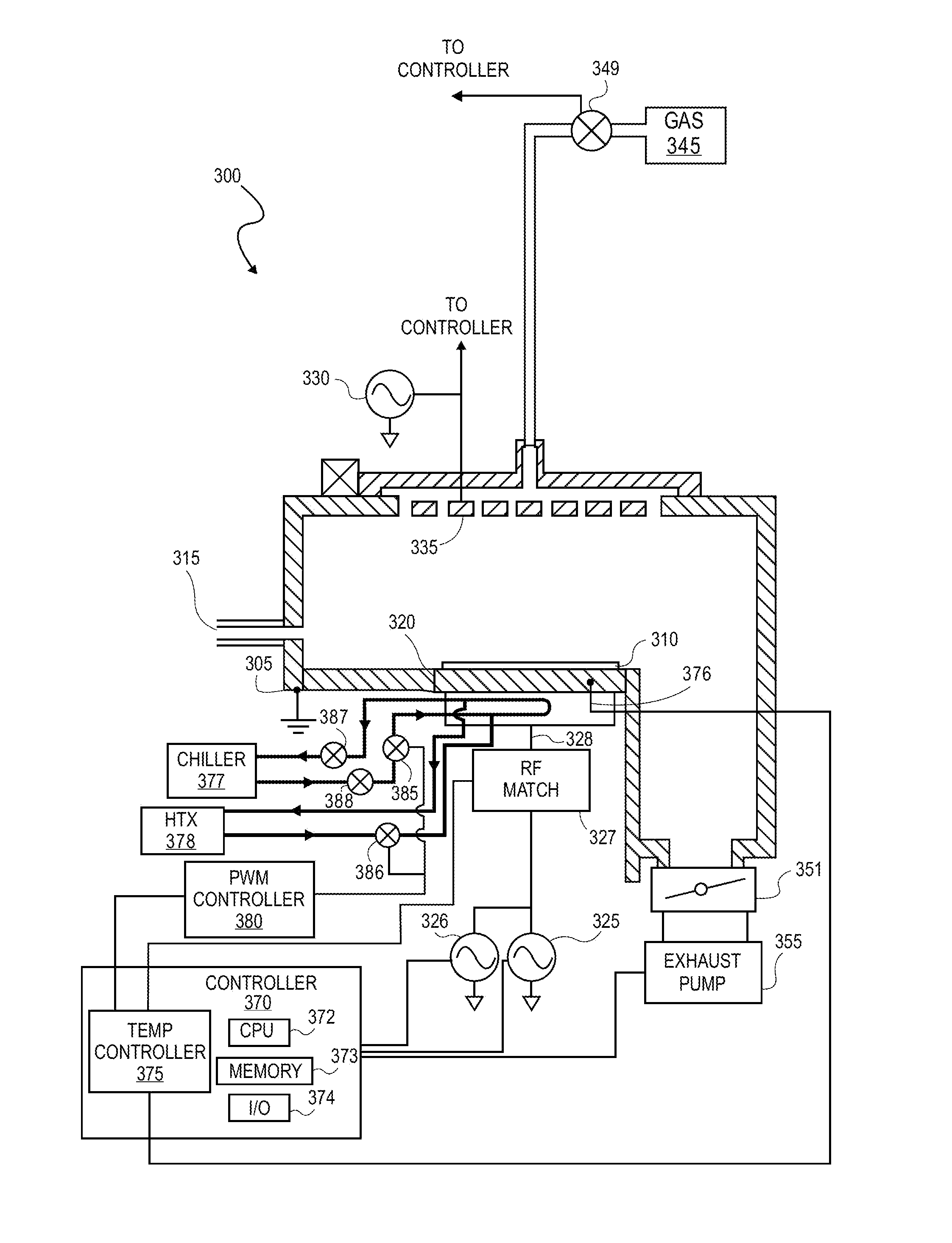
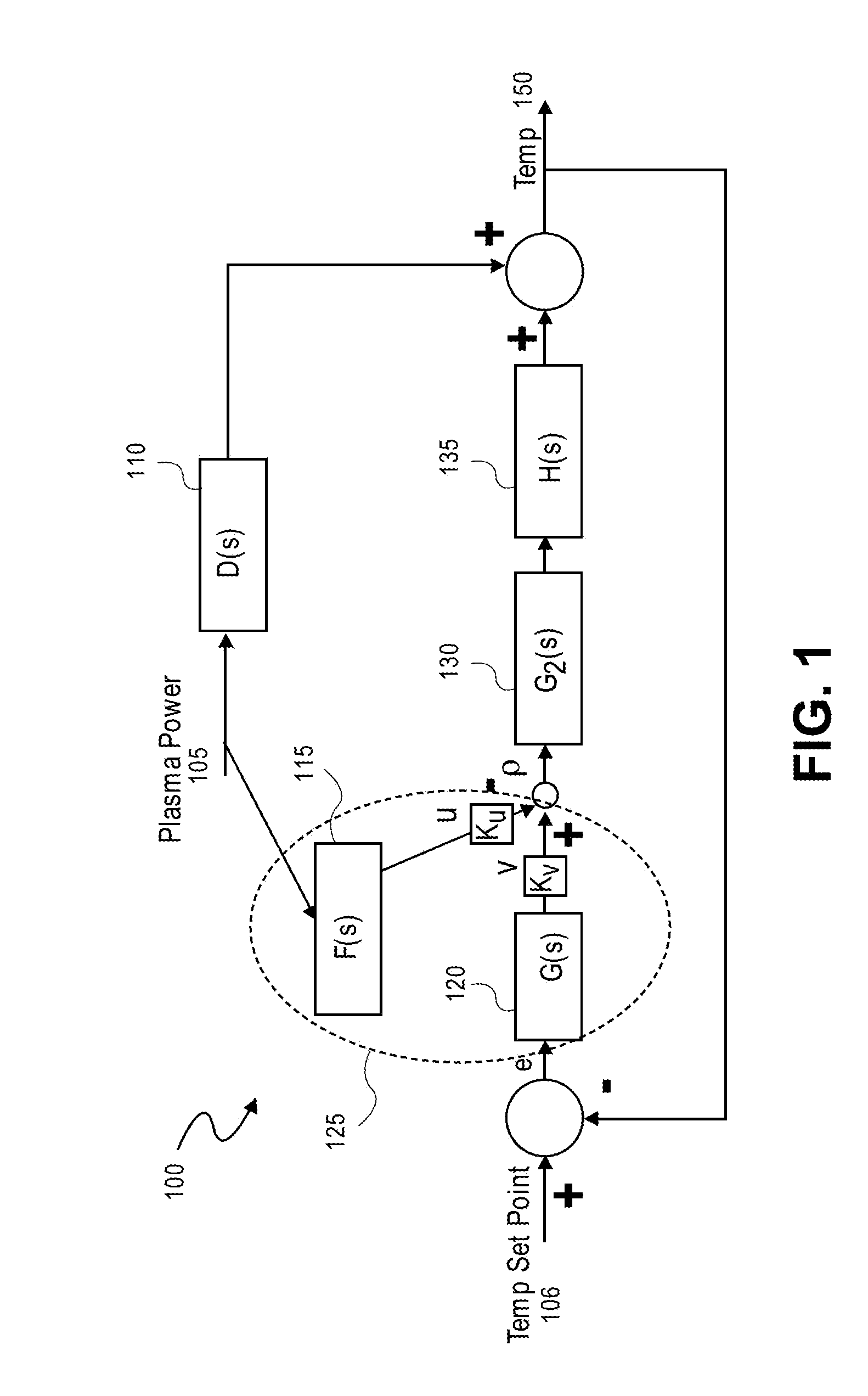
[0008]Methods and systems for controlling a process or chamber component temperature as a plasma process is executed by plasma processing apparatus are described herein. In certain embodiments, methods and systems incorporate a feedforward control algorithm to advantageously reduce steady state errors and improve response times.

Problems solved by technology

Steady state errors occur with simple feedback control unless a large enough integrator is used.
In simple Proportional control there is always steady state error in the presence of external disturbance (unless proportional gain is infinity).
However use of large integral control results in poor transients with large overshoots and requires and long settling times. Unlike mass flow controllers (MFCs) which have short response times requiring only a few seconds to converge to a setpoint, chamber component temperatures, such as an electrostatic chuck or showerhead temperature, may require 30 seconds or more to stabilize when perturbed during a plasma process due to the significant thermal mass of the chuck, etc.
As such, to most quickly compensate for disturbances, large integrator values may be utilized in the feedback controller which has the undesirable side effect of making the temperature control more unstable.
Furthermore, to accommodate increasingly complex film stacks, many plasma processes expose a workpiece to a number of sequential plasma conditions within a same processing chamber.
Operations in such in-situ recipes (performed within a single manufacturing apparatus rather than in separately tuned systems) may require temperature setpoints spanning a wide range which introduces a non-linearity into the system such that perturbations or disturbances occurring while the temperature is near a system extreme render response times intolerable.

Method used


Image

  • Feedforward temperature control for plasma processing apparatus
  • Feedforward temperature control for plasma processing apparatus
  • Feedforward temperature control for plasma processing apparatus

Examples


Embodiment Construction

[0022]In the following detailed description, numerous specific details are set forth in order to provide a thorough understanding of embodiments of the invention. However, it will be understood by those skilled in the art that other embodiments may be practiced without these specific details. In other instances, well-known methods, procedures, components and circuits have not been described in detail so as not to obscure the present invention. Some portions of the detailed description that follows are presented in terms of algorithms and symbolic representations of operations on data bits or binary digital signals within a computer memory. These algorithmic descriptions and representations may be the techniques used by those skilled in the data processing arts to convey the substance of their work to others skilled in the art.

[0023]An algorithm or method is here, and generally, considered to be a self-consistent sequence of acts or operations leading to a desired result. These inclu...


PUM

PropertyMeasurementUnit
Temperatureaaaaaaaaaa
Widthaaaaaaaaaa
Stabilityaaaaaaaaaa

Abstract

Methods and systems for controlling temperatures in plasma processing chamber with reduced controller response times and increased stability. Temperature control is based at least in part on a feedforward control signal derived from a plasma power input into the processing chamber. A feedforward control signal compensating disturbances in the temperature attributable to the plasma power may be combined with a feedback control signal counteracting error between a measured and desired temperature.

Description

CROSS-REFERENCE TO RELATED APPLICATIONS[0001]This application claims the benefit of U.S. PROVISIONAL PATENT APPLICATION 61 / 299,818 filed Jan. 29, 2010, incorporated herein by reference in its entirety for all purposes.BACKGROUND[0002]1) Field[0003]Embodiments of the present invention generally relate to plasma processing equipment, and more particularly to methods of controlling temperatures during processing of a workpiece with a plasma processing chamber.[0004]2) Description of Related Art[0005]In a plasma processing chamber, such as a plasma etch or plasma deposition chamber, the temperature of a chamber component is often an important parameter to control during a process. For example, a temperature of a substrate holder, commonly called a chuck or pedestal, may be controlled to heat / cool a workpiece to various controlled temperatures during the process recipe (e.g., to control an etch rate). Similarly, a temperature of a showerhead / upper electrode or other component may also be...

Claims


Application Information

Patent Timeline
IPC IPC(8): C23F1/08C23F1/00C23C16/50C23C16/458C23C16/52G05D23/00
CPCH05H1/0081H01J37/32935H01J37/32522H01J37/32174G05B6/02H01J37/32009H01J37/3244H01J37/32715H01J2237/334
Inventor MAHADESWARASWAMY, CHETANMERRY, WALTER R.SHOJI, SERGIO FUKUDAZHANG, CHUNLEIPATTAR, YASHASWINI B.NGUYEN, DUY D.TSONG, TINANEVIL, SHANE C.BUCHBERGER, JR., DOUGLAS A.SILVEIRA, FERNANDO M.MAYS, BRAD L.RAMASWAMY, KARTIKNOORBAKHSH, HAMID
Owner APPLIED MATERIALS INC
Learn More