Radiator fin and radiator fin component thereof

Inactive Publication Date: 2011-08-04
KUNGTIN METALLIC PRODS
View PDF6 Cites 2 Cited by
  • Summary
  • Abstract
  • Description
  • Claims
  • Application Information

AI Technical Summary

Benefits of technology

[0007]Another object of the present invention is to provide a radiator fin component that possesses a big heat conducting interface between radiator fins and the corresponding base by means of increasing an interface for heat elimination, providing multiple heat elimination paths, achieving a capability of preventing the radiator fins falling off from the base, and is easy to be pinched and formed.
[0013]The two heat conducting vanes in the present invention, which are in porous structure, replace the conventional conducting vanes made of aluminum plates, and the heat conducting vanes of the present invention can bear high-pressure. Further, the two heat conducting vanes are face to face, allowing ventilation regions with multiple heat conducting paths, thereby providing a good cooling effect.
[0016]The radiator fin component of the present invention has track grooves which have narrow tops and wider bases assuming shapes in the base, and the riveting regions of the radiator fin are provided corresponding to the track grooves assuming shapes, and the riveting regions of the radiator fin can be pushed into the corresponding track grooves, so the possibility of the radiator fins falling off from the base is eliminated. The radiator fin component has big heat conducting regions between the radiator fins and the track grooves of the base and thus the heat conducting effect is greatly improved On the other hand, suitable pressure can be applied to the top end of the radiator fins to help the heat elimination component in extrusion forming, and the method of extrusion forming is different from the conventional forming method and is simple and convenient to operate.

Problems solved by technology

The heat conducting methods of conventional heat elimination devices which are used in the fields of chips, semiconductors, and other electric elements for cooling are many, and the heat conductors are often made of aluminum by extrusion forming methods or joints composed of aluminum vanes and copper vanes, so the areas and strength of the conventional heat elimination devices for cooling are limited.
On the other hand, the interfaces in contact with air are quite small, so the conventional heat elimination devices are high-priced, while the effect of heat elimination of the conventional heat elimination devices is not good.
However, the pinching method of the conventional component increases the possibility of radiator fins falling off from the base, and the small cooling interface between radiator fins and the base greatly decreases the cooling effect.
Furthermore, the construction of the conventional heat elimination component is complicated and inconvenient to operate.

Method used


Image

  • Radiator fin and radiator fin component thereof
  • Radiator fin and radiator fin component thereof
  • Radiator fin and radiator fin component thereof

Examples


Embodiment Construction

[0025]Below, the preferred embodiments of the present invention are described in detail incorporating the drawings.

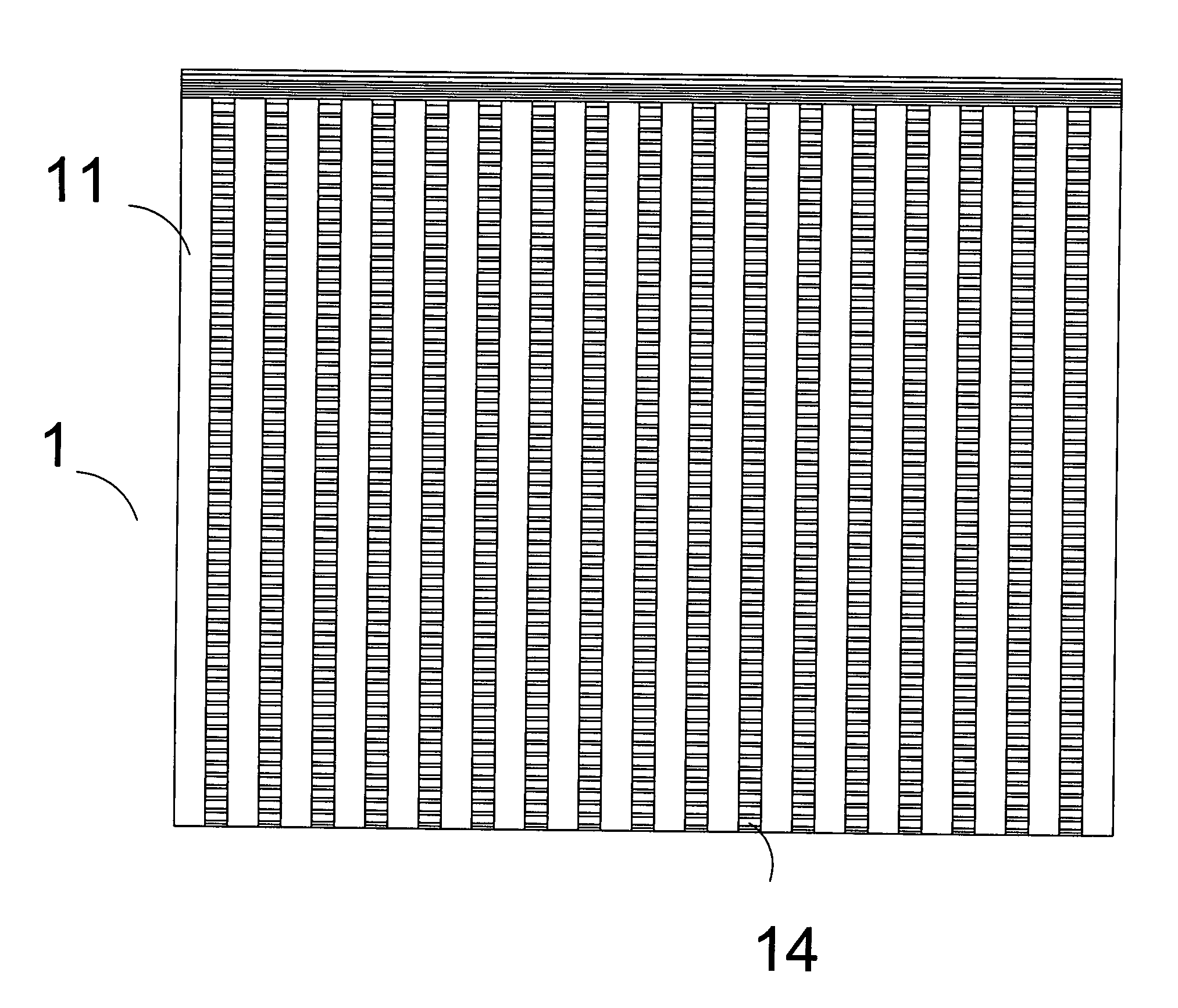
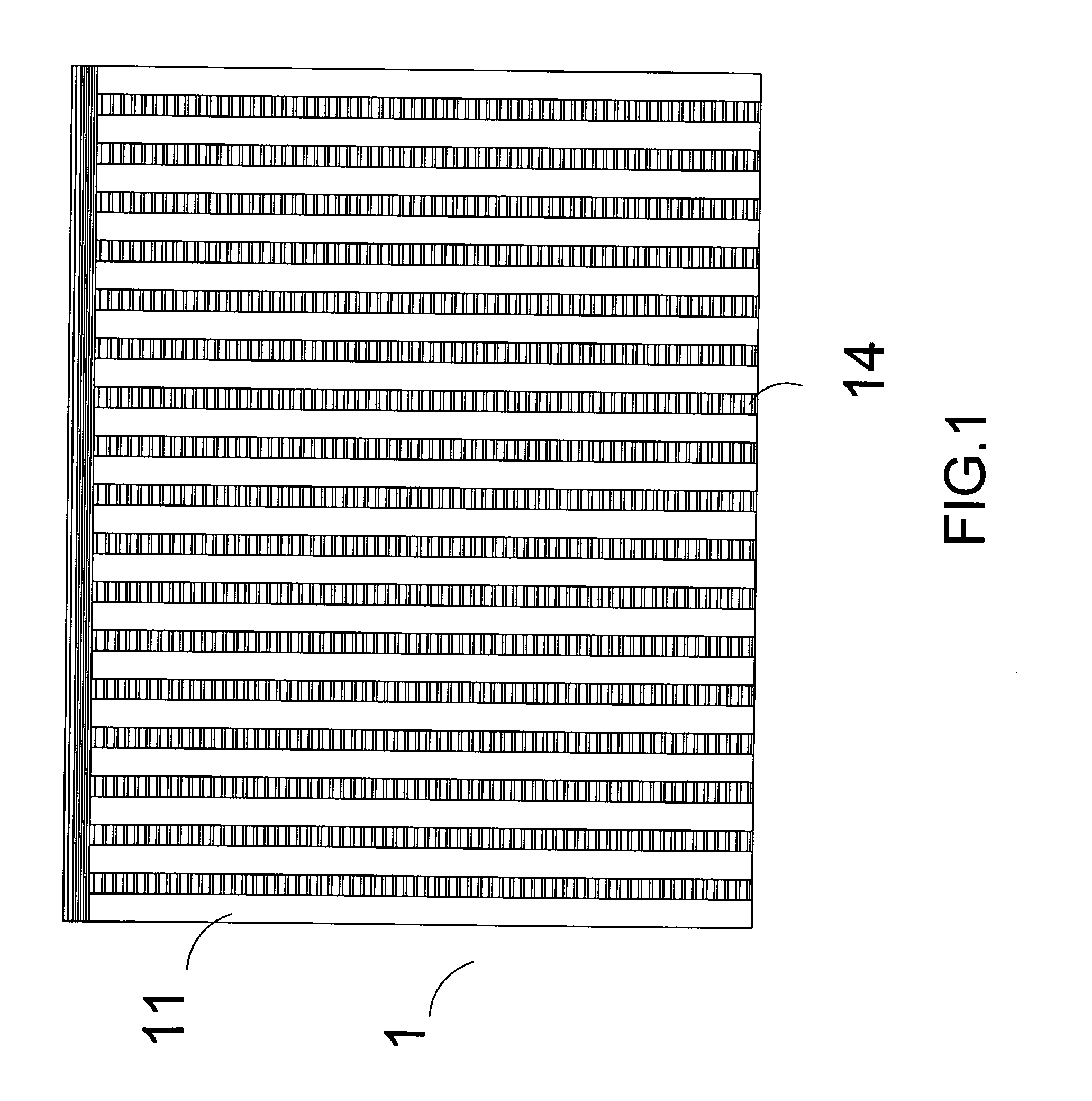
[0026]Referring to FIG. 1 to FIG. 2 of the drawings, a radiator fin according to the first preferred embodiment of the present invention is illustrated. The radiator fin comprises two heat conducting vanes 11, 12 which are joined end to end and top to top, and the two heat conducting vanes 11, 12 are made of aluminum or other materials which possess a high coefficient of heat conduction and multiple strength vanes 13 next to inner walls of the heat conducting vanes 11, 12 are provided in the space between the two heat conducting vanes. The two heat conducting vanes 11, 12 and the strength vanes 13 are all in porous structure. Further, the two heat conducting vanes 11, 12 provide allowing ventilation regions correspondingly, and the allowing ventilation regions are breather holes or continuing breather grooves 14 correspondingly provided in the heat conducting vanes. Acc...


PUM


Abstract

One or more radiator fins each includes two heat conducting vanes which are joined end to end and top to top. There are multiple strength vanes next to inner walls of the heat conducting vanes in the space between two heat conducting vanes. The radiator fins are made into porous structure and bear high pressure. The two heat conducting vanes have corresponding allowing ventilation region and the radiator fins have multiple heat conducting paths and can achieve a very good cooling effect. A radiator fin component includes multiple radiator fins and a base, wherein multiple track grooves are provided in the base. The radiator fins possess rivet joints corresponding to rivet joints of groove regions of the base. After the rivet joints are pushed into the corresponding grooves, downward pressure can be applied to the top of the radiator fins fixing the radiator fins in the base.

Description

BACKGROUND OF THE PRESENT INVENTION[0001]1. Field of Invention[0002]The present invention relates to a radiator fin for conducting heat, and more particularly to a radiator fin which is used in the fields of chips, semiconductors, and other electric elements for cooling. Further, the present invention also includes a radiator fin component which comprises the radiator fins and a base.[0003]2. Description of Related Arts[0004]The heat conducting methods of conventional heat elimination devices which are used in the fields of chips, semiconductors, and other electric elements for cooling are many, and the heat conductors are often made of aluminum by extrusion forming methods or joints composed of aluminum vanes and copper vanes, so the areas and strength of the conventional heat elimination devices for cooling are limited. On the other hand, the interfaces in contact with air are quite small, so the conventional heat elimination devices are high-priced, while the effect of heat elimi...

Claims


Application Information

Patent Timeline
IPC IPC(8): F28F7/00
CPCF28F7/00F28D2021/0035F28F9/262H01L23/3672F28F3/02F28F1/16F28D1/0233
Inventor LIU, CHUN TING
Owner KUNGTIN METALLIC PRODS
Why Eureka
Try Eureka