
Alkylation process comprising monitoring ionic liquid catalyst acidity

a technology acidity, which is applied in the direction of organic chemistry, physical/chemical process catalysts, organic compounds/hydrides/coordination complex catalysts, etc., can solve the problems of deactivation, loss of activity, and need to be replaced, so as to achieve sufficient reaction, efficiently regenerated and recycled, and the effect of monitoring the deactivation level of ionic liquid catalys

Inactive Publication Date: 2011-07-28
CHEVROU USA INC
View PDF12 Cites 18 Cited by
  • Summary
  • Abstract
  • Description
  • Claims
  • Application Information

AI Technical Summary

Benefits of technology

Among other factors, it has been discovered that titration can be used as a technique to successfully monitor the deactivation level of an ionic liquid catalyst. The use of titration in the process for determining ionic liquid catalyst deactivation as disclosed herein enables commercial exploitation of ionic liquid catalysts in alkylation and other chemical processes employing ionic liquid catalysts during which ionic liquid catalysts become deactivated. Due to such deactivation, these chemical processes require monitoring ionic liquid catalyst deactivation in order to maintain sufficient reaction. Ionic liquid catalysts are also expensive to replace. Thus, the use of ionic liquid catalysts in these chemical processes is economically feasible only when the catalysts can be efficiently regenerated and recycled. The process for determining ionic liquid catalyst deactivation as disclosed herein and the other processes utilizing an embodiment of such process for determining ionic liquid catalyst deactivation can maintain sufficient reaction during ionic liquid deactivating chemical processes. The present processes can also permit efficient regeneration of ionic liquid catalysts and recycling of such regenerated catalysts.

Problems solved by technology

As a result of use, ionic liquid catalysts can become deactivated, i.e. lose activity, and may eventually need to be replaced.
For example, as aluminum trichloride in aluminum trichloride-containing ionic liquid catalysts becomes complexed with conjunct polymers, the activity of these ionic liquid catalysts becomes impaired or at least compromised.
Conjunct polymers may also become chlorinated and through their chloro groups may interact with aluminum trichloride in aluminum trichloride-containing catalysts and therefore reduce the overall activity of these catalysts or lessen their effectiveness as catalysts for their intended purpose.

Method used


Image

  • Alkylation process comprising monitoring ionic liquid catalyst acidity
  • Alkylation process comprising monitoring ionic liquid catalyst acidity
  • Alkylation process comprising monitoring ionic liquid catalyst acidity

Examples


example 1

Preparation of N-Butylpyridinium Chloroaluminate Catalyst

N-butylpyridinium chloroaluminate (C5H5C4H9Al2Cl7) ionic liquid catalyst was purchased. The catalyst had the following composition.

Wt % Al12.4Wt % Cl56.5Wt % C24.6Wt % H3.2Wt % N3.3

example 2

C4 Olefin and Isobutane Alkylation

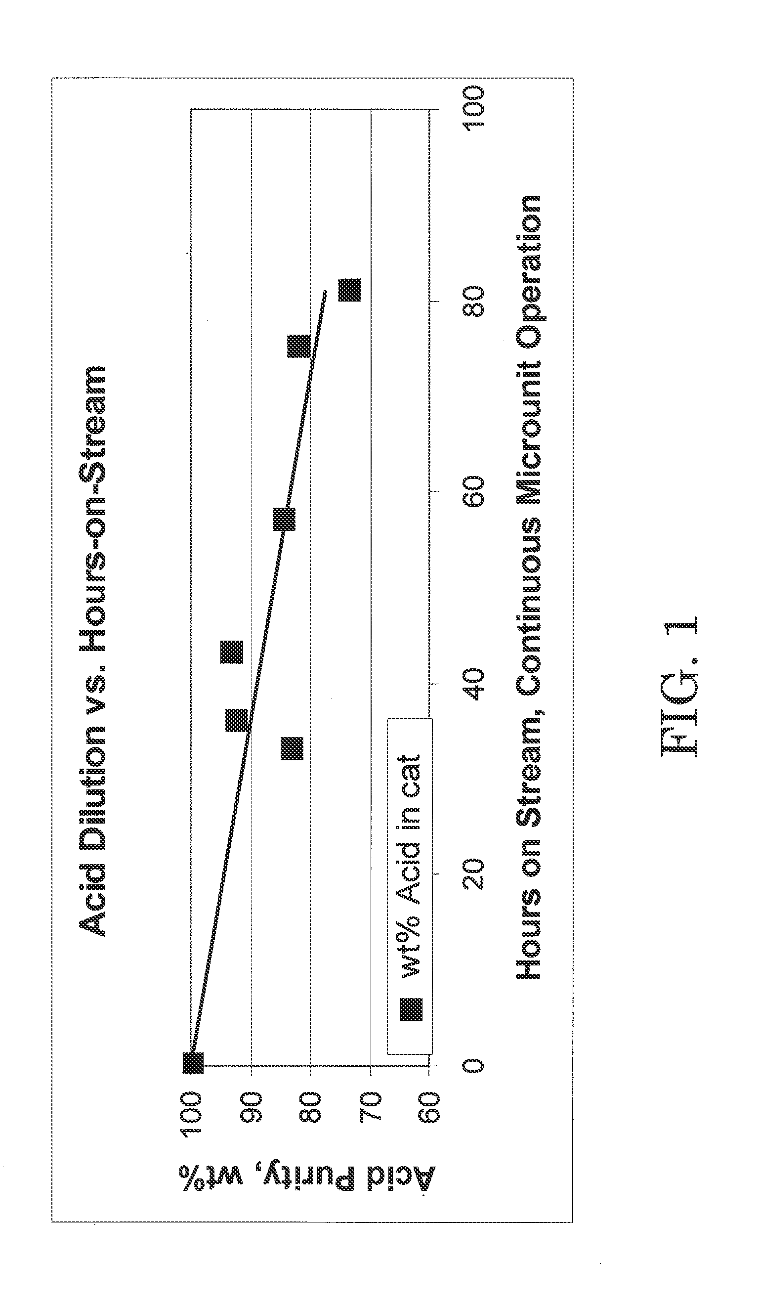
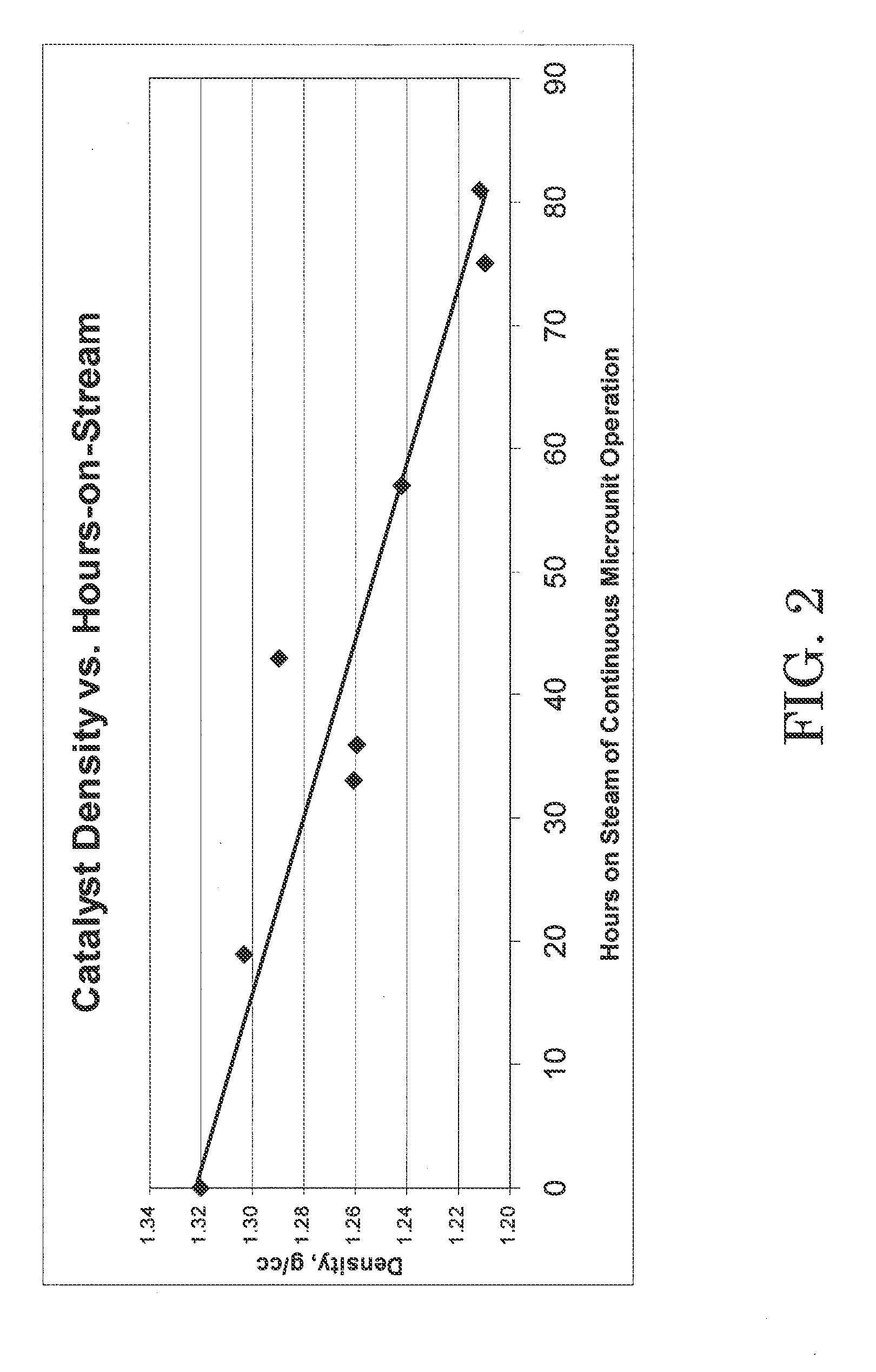
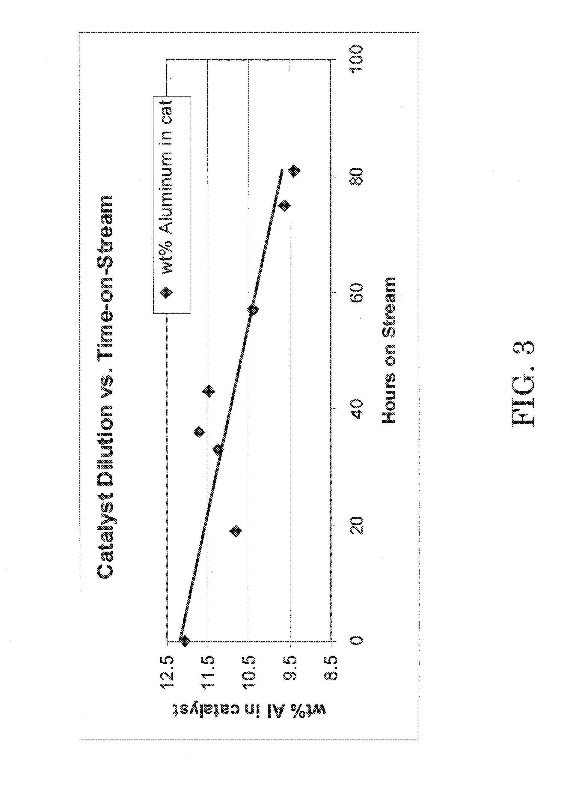
C4 olefin alkylation with isobutane was performed in a 100 cc continuously stirred tank reactor. A mixture of isobutane and 2-butene having a 8:1 molar ratio was fed to the reactor while vigorously stirring at 1600 RPM. The chloroaluminate ionic liquid catalyst of Example 1 was fed to the reactor via a second inlet port targeting to occupy 8 vol % in the reactor. A small amount of anhydrous HCl gas was added to the process. The average residence time (combined volume of feeds and catalyst) was about 8 minutes. The outlet pressure was maintained at 100 psig using a backpressure regulator. The reactor temperature was maintained at 0° C. using external cooling. The reactor effluent was separated in a 3-phase separator into C4-gas, an alkylate hydrocarbon phase, and the ionic liquid catalyst. The ionic liquid catalyst was recycled back to the reactor continuously. The amount of catalyst in the system was about 220 g, and the catalyst circulation was 100...

example 3

Measurement of Properties of Fresh and Used Catalyst

The total acidity of the fresh catalyst used in Example 2 and the used catalyst drained in Example 2 was determined using an acid / base titration method as follows. An automatic potentiometric titrator was set up using 100 mL of nitrogen purged, de-aerated water and isopropyl alcohol mixture in a beaker. The solution in the beaker was blanketed with dry nitrogen gas and stirred. Using an airtight syringe, a catalyst sample was drawn to transfer approximately 0.05 g into the beaker. The weight charged to the beaker was determined by difference to the nearest 0.0001 g. The catalyst sample charged to the beaker dissolved in the water / isopropyl mixture rapidly, and the pH value of the solution decreased. The resulting solution was titrated with standardized 0.1 N KOH solution to the same potential as the blank. A well-defined inflection point was shown in the resulting titration curve around pH 7. From the amount of KOH solution consume...


PUM

PropertyMeasurementUnit
Massaaaaaaaaaa
Fractionaaaaaaaaaa
Densityaaaaaaaaaa

Abstract

A process for determining ionic liquid catalyst deactivation including (a) collecting at least one sample of an ionic liquid catalyst; (b) hydrolyzing the at least one sample to provide at least one hydrolyzed sample; (c) titrating the at least one hydrolyzed sample with a basic reagent to determine a volume of the basic reagent necessary to neutralize a Lewis acid species of the ionic liquid catalyst; and (d) calculating the acid content of the at least one sample from the volume of basic reagent determined in step (c) is described. Processes incorporating such a process for determining ionic liquid catalyst deactivation are also described. These processes are an alkylation process, a process for controlling ionic liquid catalyst activity in a reaction producing by-product conjunct polymers, and a continuous process for maintaining the acid content of an ionic liquid catalyst at a target acid content in a reaction producing by-product conjunct polymers.

Description

FIELD OF ARTThe processes described herein relate to determining ionic liquid catalyst deactivation. More particularly, the processes described herein involve determining ionic liquid catalyst deactivation by titrating one or more samples of the ionic liquid catalyst with a basic reagent.BACKGROUNDAn alkylation process, which is disclosed in U.S. Pat. No. 7,432,408 (“the '408 publication”), involves contacting isoparaffins, preferably isopentane, with olefins, preferably ethylene, in the presence of an ionic liquid catalyst to produce gasoline blending components. The contents of the '408 patent are incorporated by reference herein in its entirety.An ionic liquid catalyst distinguishes this novel alkylation process from conventional processes that convert light paraffins and light olefins to more lucrative products such as the alkylation of isoparaffins with olefins and the polymerization of olefins. For example, two of the more extensively used processes to alkylate isobutane with ...

Claims


Application Information

Patent Timeline
IPC IPC(8): C07C2/58
CPCB01J31/0284Y10T436/145555C07C2/58C10G11/02C10G29/06C10G29/205C10G50/00B01J31/40G01N31/16B01J27/06B01J27/125B01J31/00G01N31/10C07C9/16Y02P20/584
Inventor TIMKEN, HYE KYUNGPATHIPARAMPIL, ANNIE T.
Owner CHEVROU USA INC
Learn More