
Systems and method for providing in-flight broadband mobile communication services

a mobile communication and broadband technology, applied in the field of ground-based wireless cellular communication systems, can solve the problems of high latency, negative impact on service quality, and high cost of the system

Inactive Publication Date: 2011-07-28
RPX CORP
View PDF12 Cites 215 Cited by
  • Summary
  • Abstract
  • Description
  • Claims
  • Application Information

AI Technical Summary

Benefits of technology

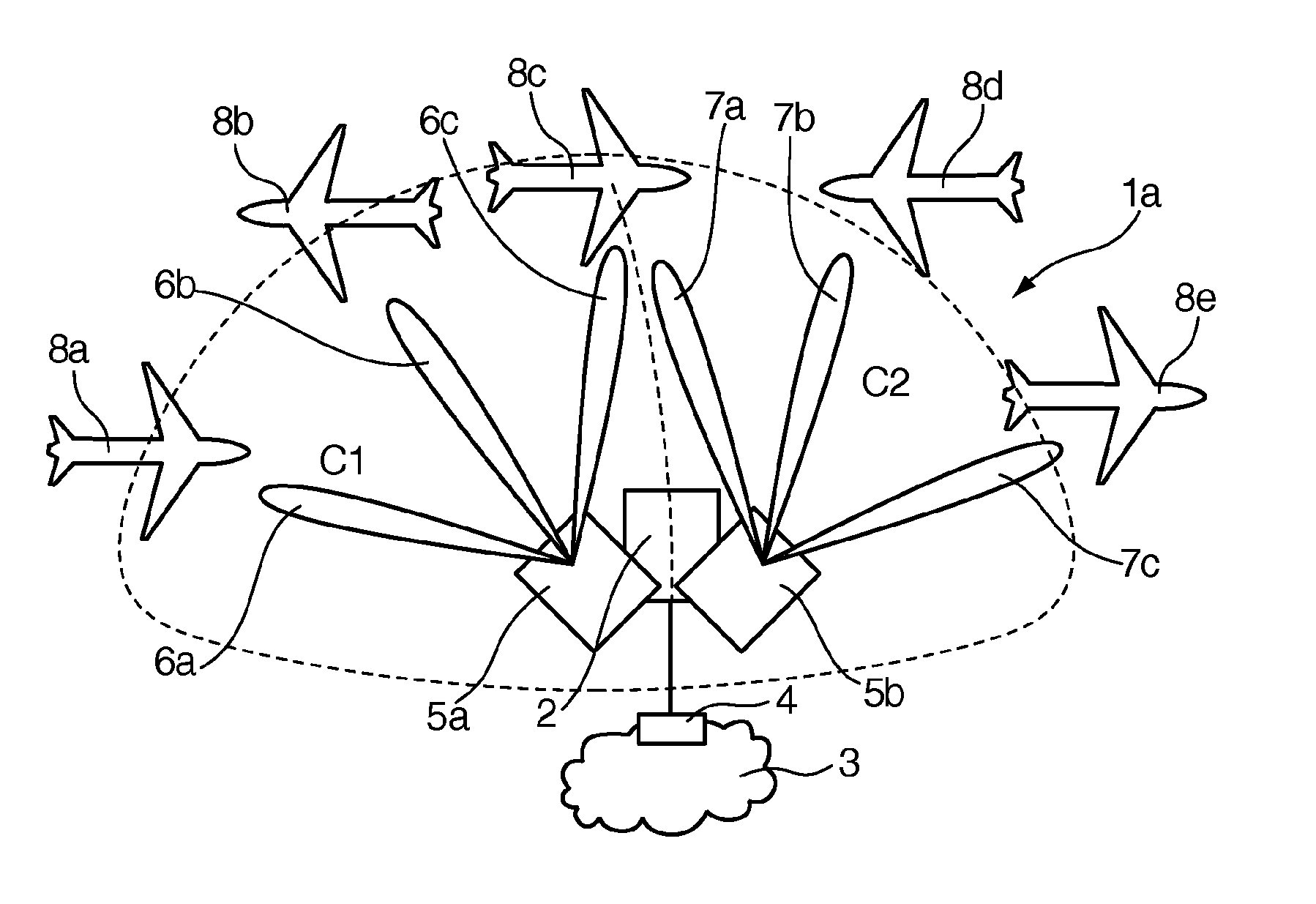
[0007]The inventive ground-based communication system makes use of the spatial separation of the served airplanes by using two-dimensional beamforming at the ground-based base stations. The term “two-dimensional beamforming” refers to beamforming in two out of the three spherical coordinates, i.e. in the azimuth and elevation direction, whereas conventional (one-dimensional) beamforming is restricted to only one spherical coordinate (azimuth). Thus, in addition to conventional TDMA and FDMA, two-dimensional beamforming enables spatial-division multiple-access (SDMA), i.e. spatial reuse of the available transmission resources within one cell, improving the average as well as the peak data throughput per cell. Further, the two-dimensional beamforming leads to a beamforming gain for the receiver signal-to-noise-and-interference ratio (SINR) in both the ground-to-air and air-to-ground direction, and the data throughputs of the individual links are also improved.

Problems solved by technology

However, such a system is expensive and typically has very high latency, thus having a negative impact on service quality.
Moreover, existing L-band solutions do not offer the capacity required for upcoming air traffic demands.
However, these multiple-access schemes do not account for the spatial separation of the served airplanes within one cell.
Thus, these schemes do not reach the theoretically possible spectrum efficiency.

Method used


Image

  • Systems and method for providing in-flight broadband mobile communication services
  • Systems and method for providing in-flight broadband mobile communication services

Examples


Embodiment Construction

[0034]FIG. 1 shows a ground-based base station 2 of a ground-based wireless cellular communication system 1a. The ground-based base station 2 may be connected to further base stations (not shown) of the ground-based communication system 1a which spread over the service area of the ground-based communication system 1a. Depending on the architecture of the ground-based wireless communication system / network, the base stations are interconnected or connected to controllers for backhauling of data and signaling. For providing access to a computer network, the ground-based base station 2 is connected to a core (computer) network 3 by a gateway 4. In this respect, the ground-based communication system 1a is very similar to common cellular mobile communication systems. It will be understood that instead of a computer network for data traffic, a voice network for voice traffic may be provided. Of course, voice communications may be treated as data, for example when using Voice over IP.

[0035]...


PUM


Abstract

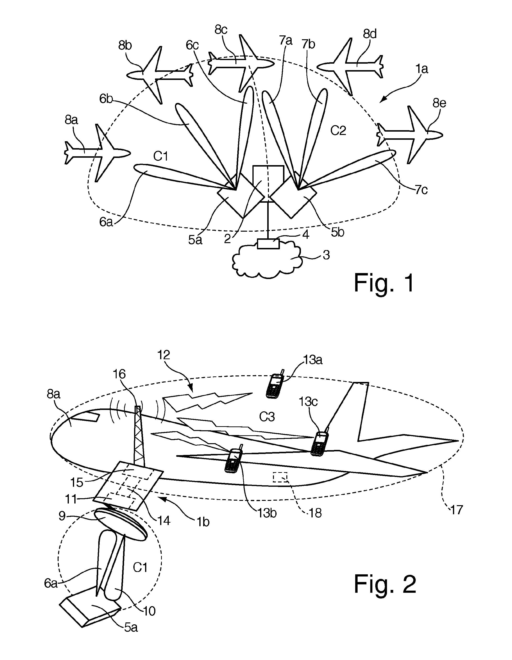
The invention relates to a ground-based wireless cellular communication system (1a) for providing in-flight broadband mobile communication services, comprising: at least one ground-based base station (2) adapted for generating at least one cell (C1, C2) defining a solid angle of the space surrounding the base station (2), the ground- based base station (2) further comprising at least one antenna array (5a, 5a) using two-dimensional-beamforming for generating at least one beam (6a-c, 7a-c) for serving at least one airplane (8a-c, 8c-e) in the space covered by the at least one cell (C1, C2) using spatial-division multiple access, SDMA. The invention also relates to an airplane equipment for providing in-flight broadband mobile communication services, comprising: at least one antenna for exchange of user data with the ground-based wireless cellular communication system (1a), a transceiver unit connected to the at least one antenna for handling the air-to-ground and ground-to-air communication with the ground-based wireless cellular communication system (1a), and an inside-airplane communication system for distributing the user data to and from terminals within the airplane.

Description

BACKGROUND OF THE INVENTION[0001]The invention relates to a ground-based wireless cellular communication system, to an airplane equipment being adapted to provide in-flight broadband mobile communication services, as well as to a corresponding method. The invention also relates to a communication system comprising such a ground-based wireless cellular communication system and at least one such airplane equipment.[0002]For efficiently providing broadband (and / or narrowband) communication services to airplanes (to be used by passengers, crew, and / or for automatic exchange of (airline) operational data), spectrum efficiency in the ground-to-air and air-to-ground communication should be high to offer real broadband services and to keep the number of ground-based base stations and / or required transmission resources (e.g. licensed spectrum) low while serving a large number of airplanes at the same time. Moreover, airplane passengers should be enabled to use their own regular communication...

Claims


Application Information

Patent Timeline
Patent Type & Authority Applications(United States)
IPC IPC(8): H04W4/00H04W84/02H04B7/14
CPCH04B7/185H04B7/26H04B7/18506H04W84/06
Inventor OHM, MICHAELWILD, THORSTENSCHMIDT, MICHAEL
Owner RPX CORP
Learn More