
Pitch adjustable bi-directional shovel

Inactive Publication Date: 2011-07-28
PAVLIC JOHN
View PDF40 Cites 3 Cited by
  • Summary
  • Abstract
  • Description
  • Claims
  • Application Information

AI Technical Summary

Benefits of technology

According to yet another aspect of the present disclosure, a pitch adjustable bi-directional shovel for the removal of debris from an associated debris laden surface is provided. The shovel includes a substantially flat blade including a forward edge and a rearward edge, each of the forward edge and the rearward edge of the blade having a contact surface for slideably engaging the associated debris laden surface. A pivot is secured to the blade. A handle is provided including a first end and a second end, the first end being rotatably mounted to the pivot. An adjustable retention assembly is secured to one or more of the pivot, the bla

Problems solved by technology

However, due to the compact nature of these heating systems, efficient and effective removal of the resultant byproducts or associated debris is not possible.
In general, the prior art shovel or debris removal devices do not work or perform adequately given the compact and confined nature of the debris compartment.
The confined space of the debris compartment coupled with the typically narrow access window or opening severely restricts the maneuverability of the shovel, particularly in and around the extreme ends or areas of the debris compartment or container.
For example, the corners of the compartment often present the greatest challenge since the prior art shovels either cannot reach the corners, are obstructed by the opening or access window, and / or lack the proper blade geometry to effectively scrape and pickup the associated debris.
As such, the user of such a prior art shovel can only pickup debris in a single direction.
First, the user is limited in that only debris in front of the prior art shovel can be picked up, thus neglecting everything behind the shovel.
Second, the continuous uni-directional motion of the prior art shovel tends to push the debris towards one end of the debris compartment (typically the rear portion) where it becomes even more difficult to reach and extract.
As such, several deficiencies exist with the prior art debris removal shovel devices.

Method used


Image

  • Pitch adjustable bi-directional shovel
  • Pitch adjustable bi-directional shovel
  • Pitch adjustable bi-directional shovel

Examples


Embodiment Construction

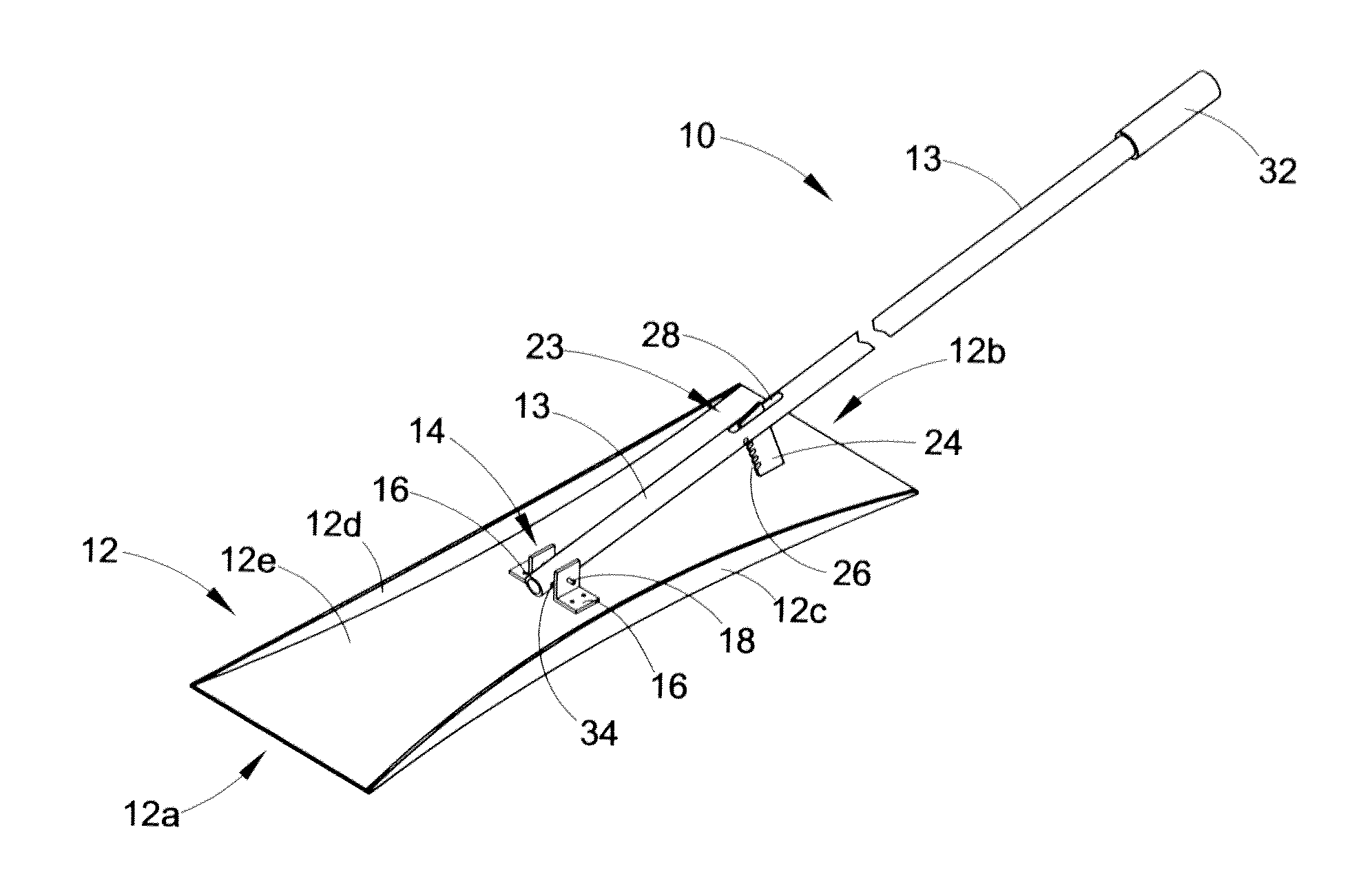
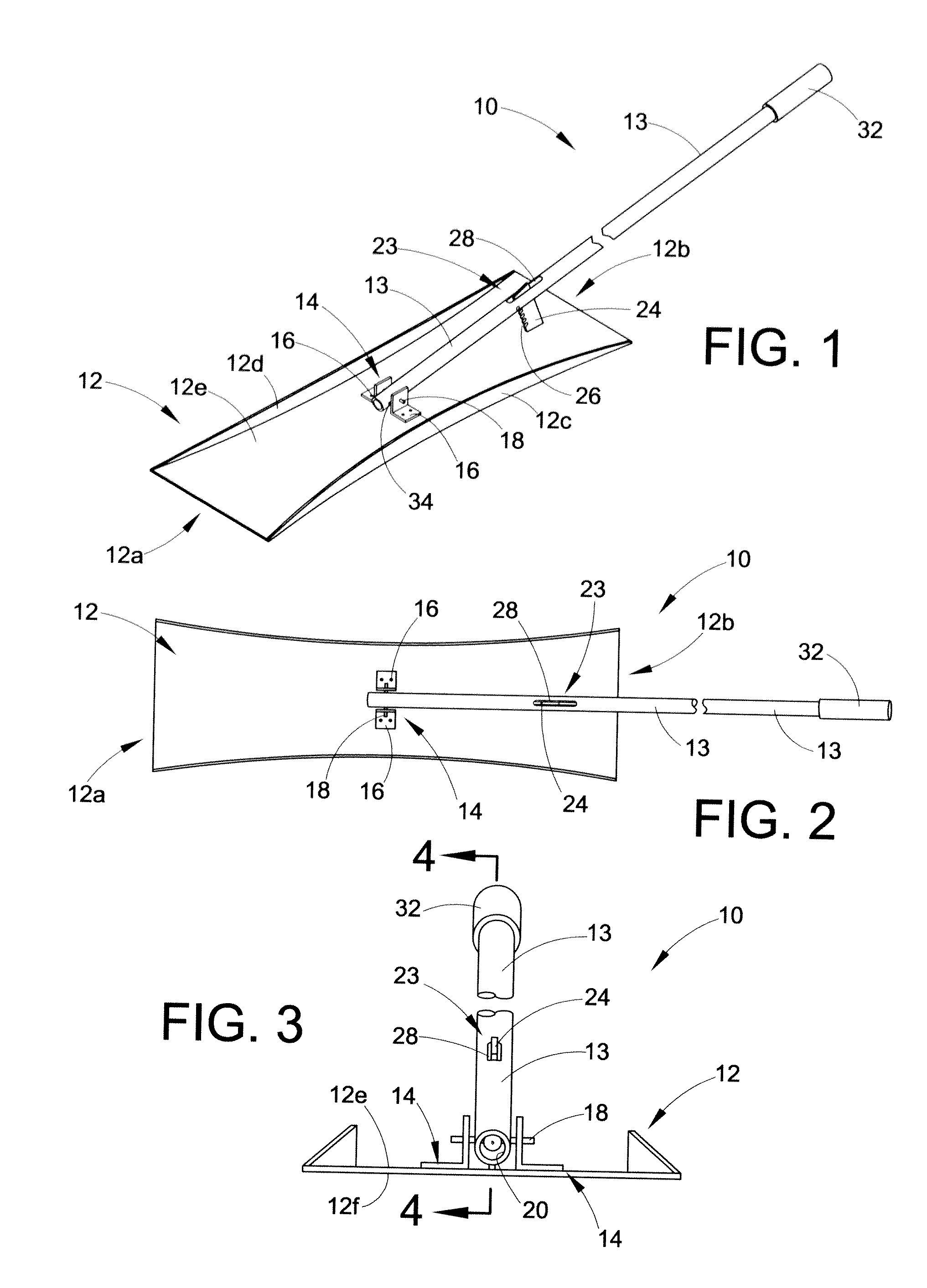
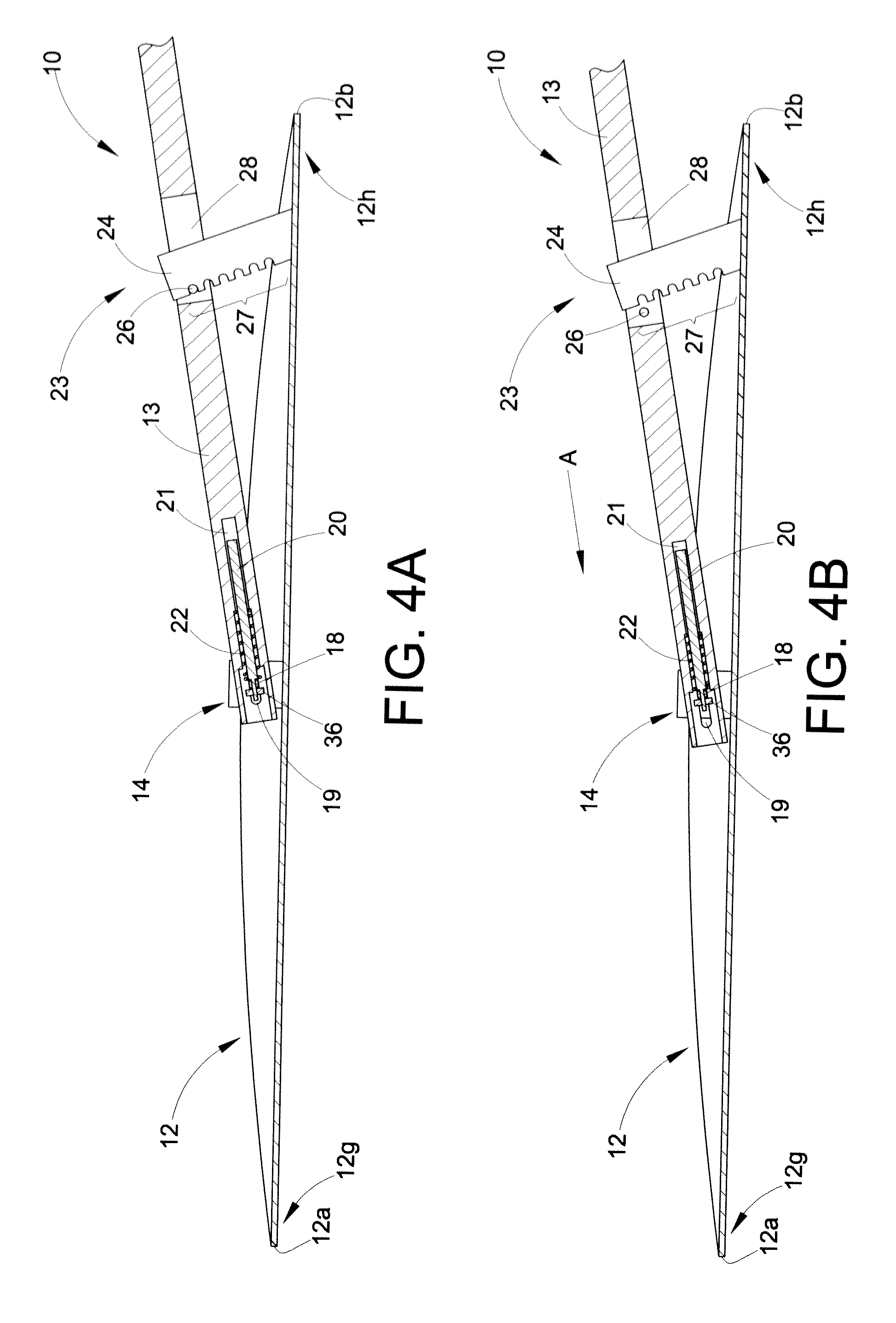
With reference to FIGS. 1-5, a first embodiment of a pitch adjustable and / or bi-directional shovel 10 is shown. The shovel 10 generally includes a body or blade 12 that can be formed into an hourglass shape from any resilient material. The blade may include multiple edges (12a, 12b), walls (12c, 12d), and contact surfaces (12e-12h) that will be discussed in more detail below. The shovel 10 further includes a handle 13 and a pivot 14. Generally, the pivot 14 is disposed between the blade 12 and the handle 13 and can be secured to the shovel 10 through the use of a pair of pivot brackets 16 and a pivot pin 18. The pivot pin 18 passes through a pivot pin guide slot 19 in the handle 13, as is illustrated in FIGS. 3-5. In addition, the handle 13 may be biased in a rearward direction through the use of an alignment pin 20 (which is disposed partially within a bore 21 in the handle 13) and a biasing element or compression spring 22. In the instant embodiment, the biasing element is dispose...


PUM


Abstract

A pitch adjustable bi-directional shovel includes a substantially flat blade including a forward edge and a rearward edge. Each edge of the blade includes a contact surface. A pivot is secured to the blade. A handle is provided including a first end and a second end, the first end being rotatably mounted to the pivot. An adjustable retention assembly is secured to one or more of the pivot, the blade, or the handle, wherein the pivot and the adjustable retention assembly cooperate to alter the pitch of the blade with respect to the handle so as maintain the blade in general parallel orientation with the associated debris laden surface. The contact surface of the forward edge slideably engages the associated debris laden surface when urged in the forward direction and the contact surface of the rearward edge slideably engages the associated debris laden surface when urged in the rearward direction.

Description

BACKGROUNDThe present application relates to the general field of shovel and debris removal devices. In particular, the present application pertains to shovel devices for the efficient removal of ash or other debris from a furnace, stove, firebox, pit, etc. However, other applications are also contemplated.With the ever rising cost of energy (e.g., electricity, oil, and natural gas) more and more individuals are returning to wood and / or coal burning heating systems to heat their homes and businesses. In addition, the use of modern electronics and controls have made these systems ever more efficient and compact, such that they can be seamlessly used in most commercial and / or residential HVAC systems. Of course, the combustion of wood and / or coal still involves the production of solid byproducts (i.e., carbon, ash, cinders, etc.) that have to be removed from an ash or debris compartment of the system on a regular basis. The prior art devices typically involve a shovel that is small en...

Claims


Application Information

Patent Timeline
IPC IPC(8): F24B15/00A01B1/02
CPCF24B15/08
Inventor PAVLIC, JOHN
Owner PAVLIC JOHN
Learn More