
Multi-cylinder hot-air engine

A hot gas engine and fuselage technology, applied in gaseous engine fuels, engine components, combustion engines, etc., can solve the problems of multi-cylinder hot gas that cannot be used uniformly, excessive use of energy, insufficient power, etc., and is conducive to maintenance and maintenance. , the effect of convenient operation

Inactive Publication Date: 2018-12-18
何海燕
View PDF0 Cites 1 Cited by
  • Summary
  • Abstract
  • Description
  • Claims
  • Application Information

AI Technical Summary

Problems solved by technology

[0002] With the development of science and the progress of society, the country has been promoting the development of advanced science and technology. Among them, in the field of engine technology, there are multi-cylinder hot gases that cannot be used uniformly, resulting in insufficient power and serious energy loss. Moreover, due to the existence of multiple cylinders, It is very important to switch the number of cylinders reasonably, otherwise it will lead to excessive use of energy and unnecessary energy loss. The device of the present invention solves this problem

Method used


Image

  • Multi-cylinder hot-air engine
  • Multi-cylinder hot-air engine
  • Multi-cylinder hot-air engine

Examples


Embodiment Construction

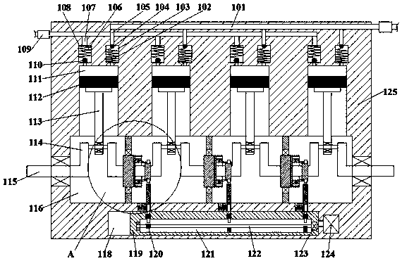
[0017] Such as Figure 1-Figure 5 As shown, the multi-cylinder heat engine of the present invention includes a fuselage 125 and a power chamber 116 arranged in the fuselage 125. The inner wall of the top of the power chamber 116 communicates with four cylinders distributed equidistantly from left to right. Cylinder 111, the top of the cylinder 111 communicates with an exhaust switch cavity 108, and the inner wall of the top of the cylinder 111 communicates with an intake switch cavity 103 located at the right end of the exhaust switch cavity 108, and the inside of the cylinder 111 is slidably fitted A piston 112 is connected, and the bottom of the piston 112 is hingedly connected with a first connecting rod 113 extending up and down. The output shaft 115 extending left and right, the output shaft 115 is provided with the crankshaft 114 at the bottom of the cylinder 111, a power connection mechanism is provided between every two crankshafts 114, and the power chamber 116 is pro...


PUM


Abstract

The invention discloses a multi-cylinder hot-air engine. The multi-cylinder hot-air engine comprises a machine body and a power cavity formed in the machine body. Four air cylinders which are distributed at equal intervals from left to right are arranged in the inner wall of the top of the power cavity in a communicating mode. Exhaust switch cavities are formed in tops of the air cylinders in a communicating mode. Air inlet switch cavities located at the right ends of the exhaust switch cavities are formed in the inner walls of the tops of the air cylinders in a communicating mode. Pistons areslidably connected into the air cylinders in a matched mode. The bottoms of the pistons are connected with first connecting rods extending up and down in a hinge joint mode. The tail ends of the bottoms of the first connecting rods stretch into the power cavity. Output shafts which extend left and right are rotatably connected into the power cavity in a matched mode, and the output shafts are provided with crank shafts located at the bottoms of the air cylinders. One power connecting mechanism is arranged between every two crank shafts.

Description

technical field [0001] The invention relates to the technical field of engines, in particular to a multi-cylinder heat engine. Background technique [0002] With the development of science and the progress of society, the country has been promoting the development of advanced science and technology. Among them, in the field of engine technology, there are multi-cylinder hot gases that cannot be used uniformly, resulting in insufficient power and serious energy loss. Moreover, due to the existence of multiple cylinders, It is very important to switch the number of cylinders reasonably, otherwise it will lead to excessive use of energy and unnecessary energy loss. The device of the present invention solves this problem. Contents of the invention [0003] The technical problem to be solved by the present invention is to provide a multi-cylinder heat engine, which can solve the above-mentioned problems in the prior art. [0004] The present invention is achieved through the f...

Claims


Application Information

Patent Timeline
IPC IPC(8): F02B43/00F02B75/20F02B75/32F02N11/00
CPCF02B43/00F02B75/20F02B75/32F02B2075/1816F02N11/00Y02T10/30
Inventor 何海燕
Owner 何海燕
Learn More