
Variable valve device for internal combustion engine

Active Publication Date: 2007-10-04
MITSUBISHI MOTORS CORP
View PDF19 Cites 2 Cited by
  • Summary
  • Abstract
  • Description
  • Claims
  • Application Information

AI Technical Summary

Benefits of technology

[0015]In view of the foregoing, an object of the invention is to provide a variable valve device for an internal combustion engine, in which facilitation of the maintenance is achieved in an oil control valve for cylinder suspending mode and an oil pump for cylinder suspending mode.
[0016]According to an aspect of the present invention, there is provided a variable valve device for an internal combustion engine comprise: an internal combustion engine body having a plurality of cylinders; a variable valve mechanism which is provided in the body and is switchable between at least two modes with oil pressure; a mode sw

Problems solved by technology

Therefore, in the lubricating oil pump, the oil pressure necessary for the switching of the variable valve mechanism is not sufficiently secured in the low engine revolution speed range.
For this reason, the running in the cylinder suspension mode is hardly performed in the low engine revolution speed range, and consequently, a cylinder suspension running range in which the running is performed in the cylinder suspension mode is significantly restricted.
However, in the structure in which the oil control valve for cylinder suspension mode and the oil pump for cylinder suspension mode are accommodated in the cylinder head, the maintenance cannot be performed in the oil control valve for cylinder suspension mode unless a rocker cover which blocks an upper portion of the cylinder head is detached.
This causes a trouble with the maintenance work of the oil control valve for cylinder suspension, in which the maintenance frequency is increased.

Method used


Image

  • Variable valve device for internal combustion engine
  • Variable valve device for internal combustion engine
  • Variable valve device for internal combustion engine

Examples


Embodiment Construction

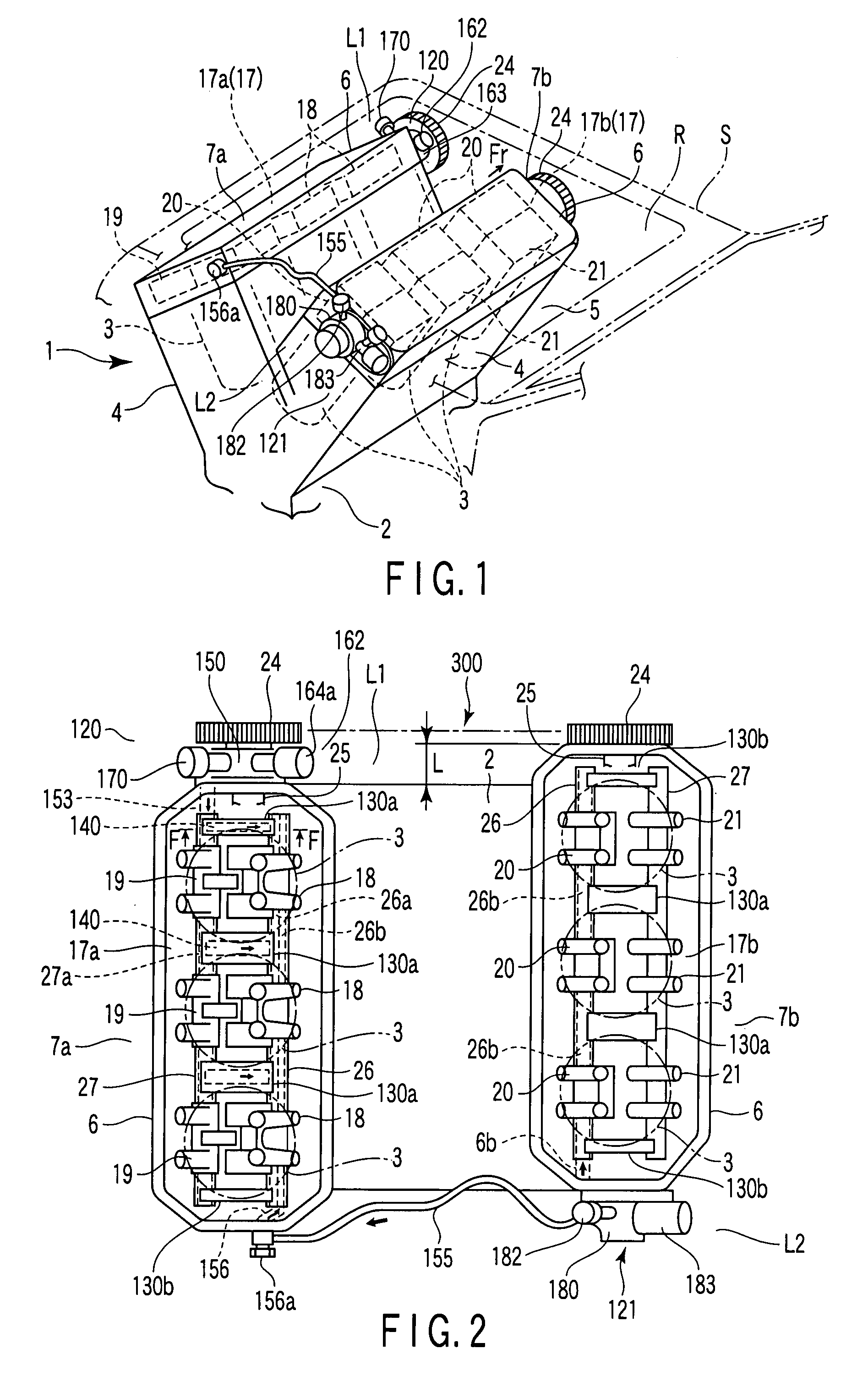
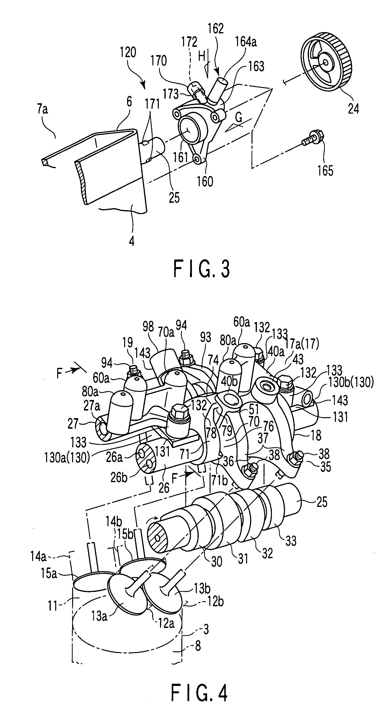
[0038]A variable valve device according to one embodiment of the invention will be described with reference to FIGS. 1 to 19. FIG. 1 is a perspective view showing a state in which an engine (internal combustion engine) where cylinder banks are separated, e.g., a V-type 6-cylinder reciprocating engine (hereinafter simply referred to as V-type engine) is mounted in an automobile body when the engine is viewed from behind. FIG. 2 is a plan view showing each bank of the engine, and FIG. 3 is a perspective view showing an oil control valve for cylinder suspension mode.

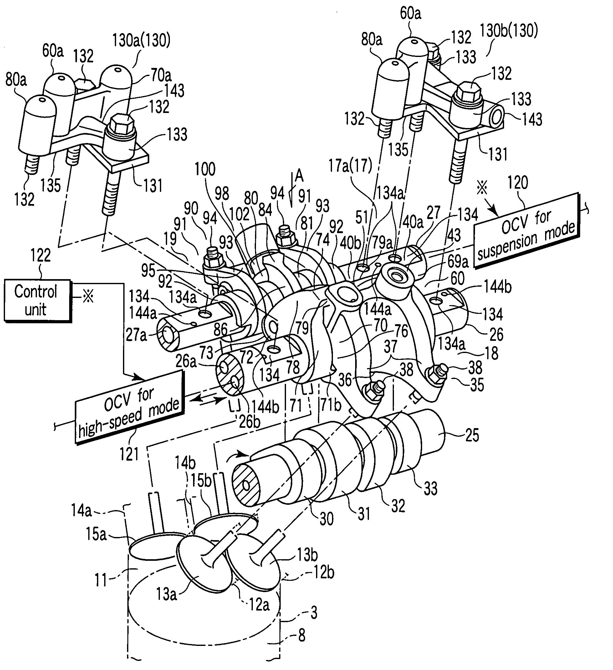
[0039]FIG. 4 is a perspective view showing inlet and exhaust variable valve devices for one cylinder of the engine. FIG. 5 is a perspective view showing a state in which a rocker shaft cap is disconnected from the variable valve device. FIG. 6 is a plan view showing the variable valve device when viewed from an arrow A of FIG. 5. FIG. 7 is a sectional view showing the rocker shaft cap taken along line F-F of FIG. 4. FIG. 8 ...


PUM


Abstract

A variable valve device for an internal combustion engine includes an internal combustion engine body having a plurality of cylinders, a variable valve mechanism which is provided in the body and is switchable between at least two modes with oil pressure, a mode switching oil control valve which switches the variable valve mechanism to each mode, and a camshaft-driven mode switching oil pump which supplies an oil pressure for switching driving to the variable valve mechanism according to the switching of the mode switching oil control valve. The mode switching oil control valve is, along with the mode switching oil pump, provided in an outer wall surface of the body.

Description

CROSS-REFERENCE TO RELATED APPLICATIONS[0001]This application is based upon and claims the benefit of priority from prior Japanese Patent Applications No. 2006-088977, filed Mar. 28, 2006; and No. 2006-088978, filed Mar. 28, 2006, the entire contents of both of which are incorporated herein by reference.BACKGROUND OF THE INVENTION[0002]1. Field of the Invention[0003]The present invention relates to a variable valve device for an internal combustion engine, which is switchable between at least two modes by control of a variable valve mechanism with an oil control valve.[0004]2. Description of the Related Art[0005]Examples of an automobile-mounted reciprocating engine (internal combustion engine) having plural cylinders include an engine which uses a variable valve device to switch to a running mode in which cylinders are partially suspended, i.e., a cylinder suspension mode in order to balance improvement of output characteristics and improvement of fuel consumption, when the engine ...

Claims


Application Information

Patent Timeline
IPC IPC(8): F01L1/34F01L1/18
CPCF01L1/053F01L13/0036F01L1/267F01L1/181
Inventor KIDO, YUSUKEMURATA, SHINICHIMORI, MASARUKOTSUJI, KENTA
Owner MITSUBISHI MOTORS CORP
Learn More