
Inductors with uniform magnetic field strength in the near-field

a near-field, magnetic field technology, applied in the field of inductors, can solve the problems of limiting the form factor and cost of the fluorescence-based molecular detection scheme, requiring bulky and expensive optical devices, and experiencing signal decay or quenching problems, etc., to achieve uniform magnetic field strength

Inactive Publication Date: 2011-07-21
CALIFORNIA INST OF TECH
View PDF11 Cites 6 Cited by
  • Summary
  • Abstract
  • Description
  • Claims
  • Application Information

AI Technical Summary

Benefits of technology

[0006]According to one aspect, the invention features an integrated inductor which includes a plurality of coils. Each of the plurality of coils is electromagnetically coupled together to form an inductor between a first inductor terminal and a second inductor terminal. At least one of the plurality of coils is disposed in a layer on an integrated structure and at least another of one of the plurality of coils is disposed in a layer of the integrated structure. One of the plurality of coils is spaced with respect to another of the plurality of coils to cause a substantially uniform magnetic field strength across a surface of the integrated inductor.

Problems solved by technology

Although widely used, fluorescence-based molecular detection schemes generally need bulky and expensive optical devices and experience signal decaying or quenching issues.
However, magnetic sensors generally need magnetic fields for external biasing and / or complicated post-processing, thus limiting their form factor and cost.
Another problem is the ability to generate a polarization magnetic field that can provides a substantially uniform transducer gain.

Method used


Image

  • Inductors with uniform magnetic field strength in the near-field
  • Inductors with uniform magnetic field strength in the near-field
  • Inductors with uniform magnetic field strength in the near-field

Examples


Embodiment Construction

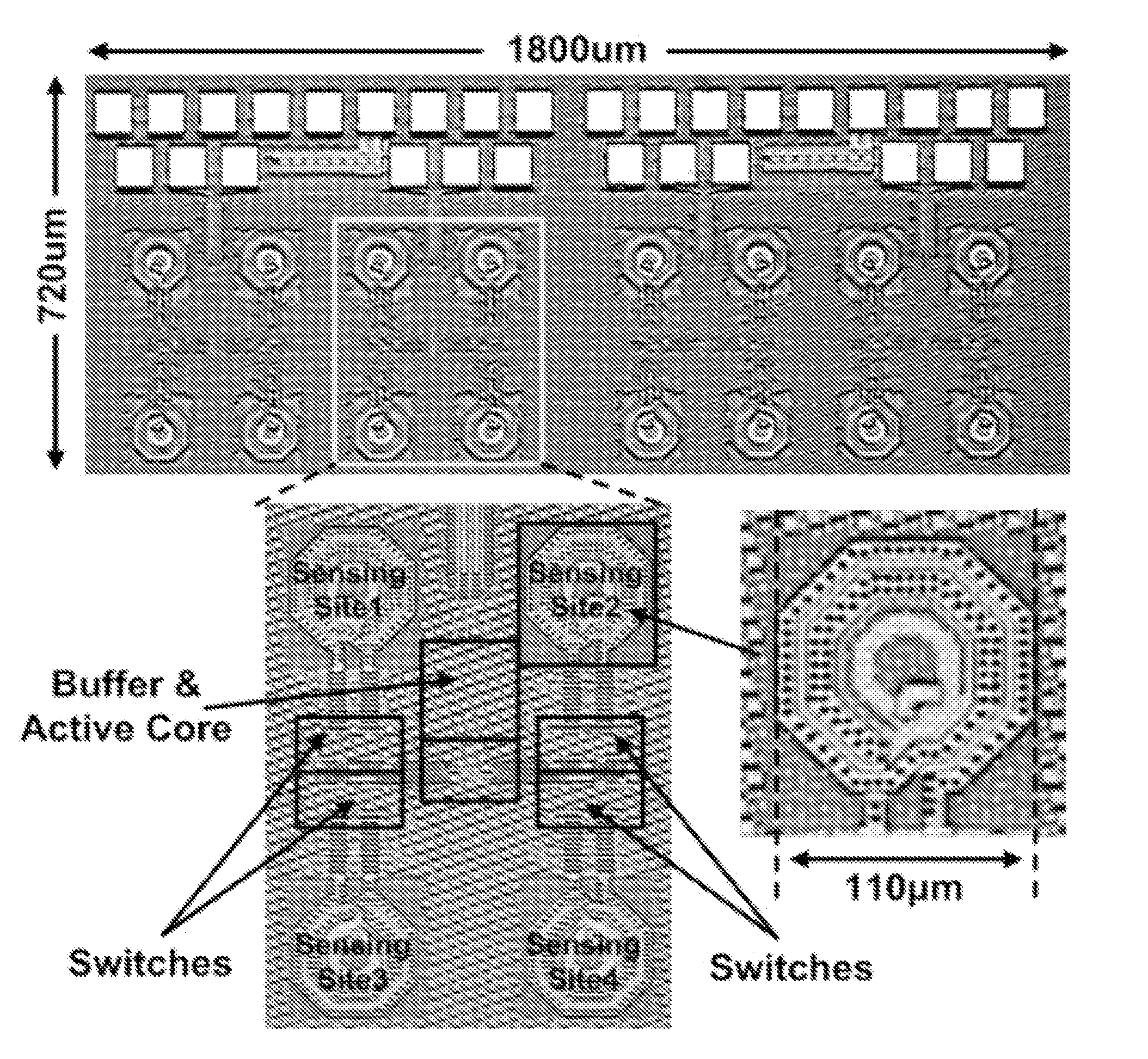
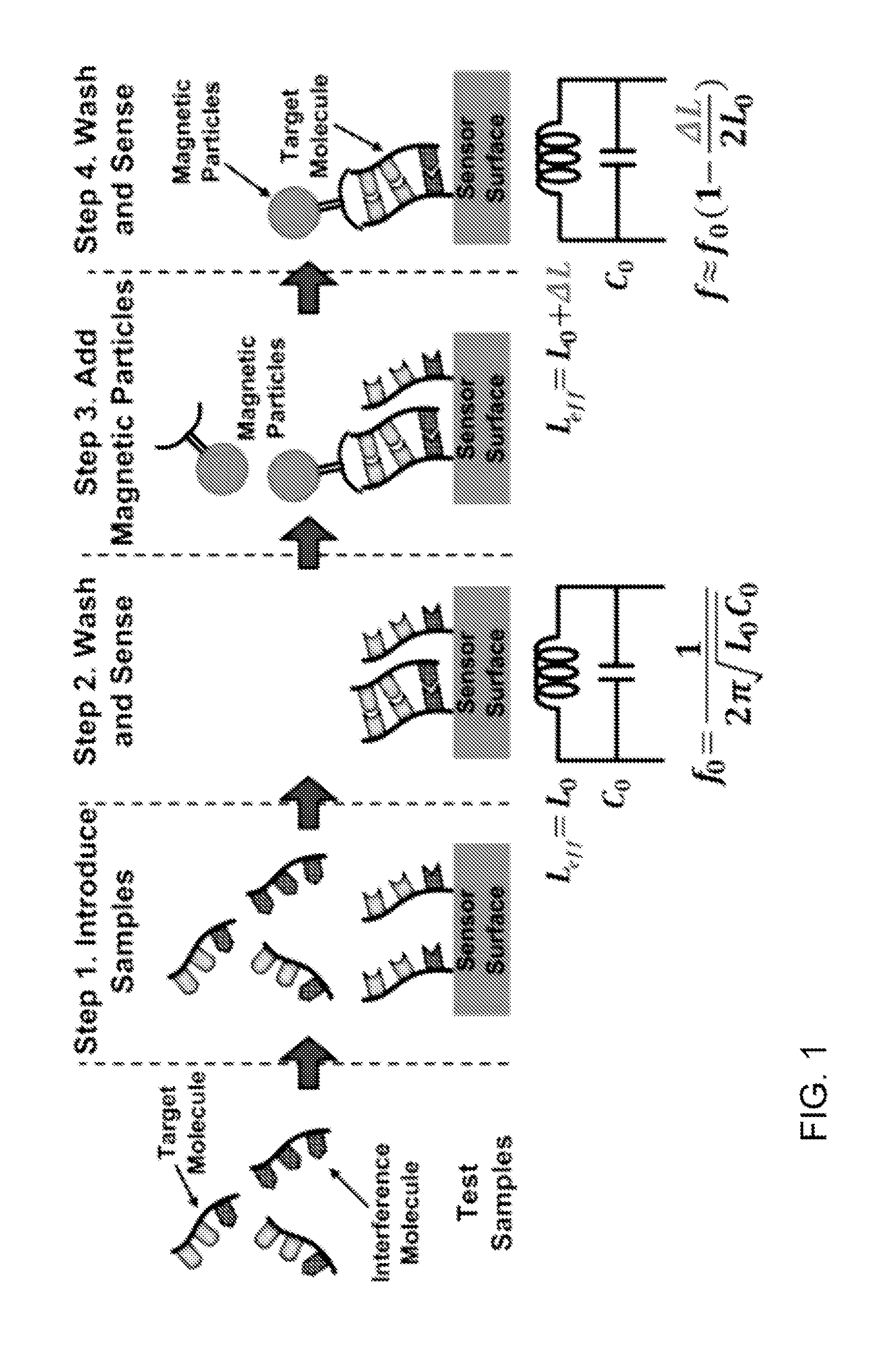
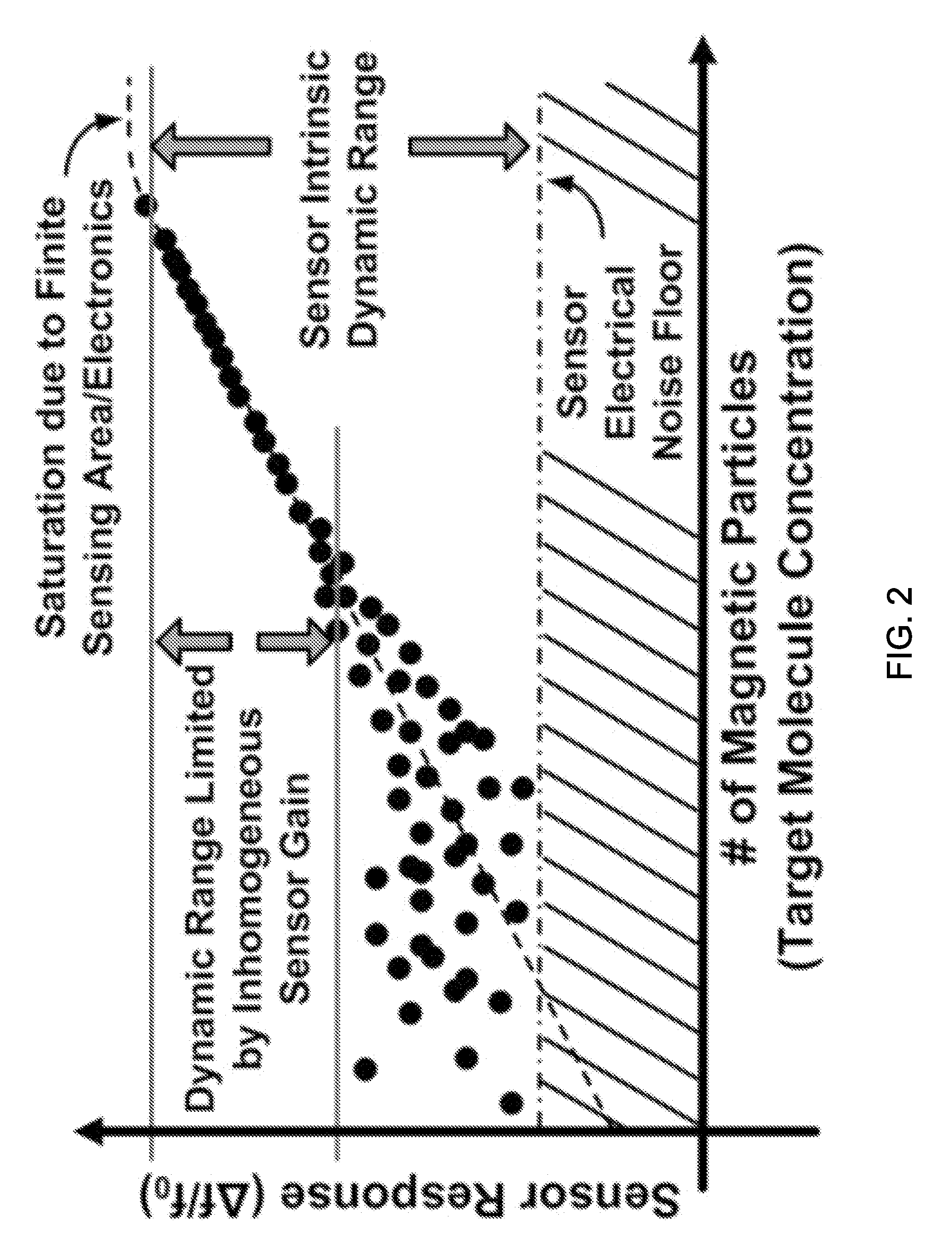
[0056]In several related applications, including co-pending U.S. patent application, EFFECTIVE-INDUCTANCE-CHANGE BASED MAGNETIC PARTICLE SENSING, Ser. No. 12 / 399,603, filed Mar. 6, 2009, co-pending U.S. patent application, FULLY INTEGRATED TEMPERATURE REGULATOR FOR BIOCHEMICAL APPLICATIONS, Ser. No. 12 / 399,320, filed Mar. 6, 2009, and co-pending U.S. patent application, A FREQUENCY-SHIFT CMOS MAGNETIC BIOSENSOR ARRAY WITH SINGLEBEAD SENSITIVITY AND NO EXTERNAL MAGNET, Ser. No. 12 / 559,517, filed Sep. 15, 2009, we described sensing components which can be used to manufacture systems that can detect from one to many magnetic particles, such as for example, microscopic magnetic particles which can be captured by molecules. Sensor systems that can detect and / or count small magnetic particles in a sample are suitable for use in a wide variety of analysis and diagnostic equipment, such as for example, medical diagnostic instruments. When some or all of such systems are integrated onto one ...


PUM

PropertyMeasurementUnit
outer diameteraaaaaaaaaa
total power consumptionaaaaaaaaaa
frequencyaaaaaaaaaa

Abstract

An integrated inductor includes a plurality of coils. Each of the plurality of coils is electromagnetically coupled together to form an inductor between a first inductor terminal and a second inductor terminal. At least one of the plurality of coils is disposed in a layer on an integrated structure and at least another of one of the plurality of coils disposed in a layer of the integrated structure. One of the plurality of coils is spaced with respect to another of the plurality of coils to cause a substantially uniform magnetic field strength across a surface of the integrated inductor. An integrated magnetic particle sensor system, an integrated inductor having a section having a different width than another section, an integrated inductor having at least one gradual transition section, and an integrated inductor having at least one floating metal structure are also described.

Description

CROSS-REFERENCE TO RELATED APPLICATIONS[0001]This application claims priority to and the benefit of co-pending U.S. provisional patent application Ser. No. 61 / 289,925, Design of Inductors with Uniform Magnetic Field Strength in the Near-Field, filed Dec. 23, 2009. This application is also related to co-pending U.S. patent application, EFFECTIVE-INDUCTANCE-CHANGE BASED MAGNETIC PARTICLE SENSING, Ser. No. 12 / 399,603, filed Mar. 6, 2009, to co-pending U.S. patent application, FULLY INTEGRATED TEMPERATURE REGULATOR FOR BIOCHEMICAL APPLICATIONS, Ser. No. 12 / 399,320, filed Mar. 6, 2009, and to co-pending U.S. patent application, A FREQUENCY-SHIFT CMOS MAGNETIC BIOSENSOR ARRAY WITH SINGLEBEAD SENSITIVITY AND NO EXTERNAL MAGNET, Ser. No. 12 / 559,517, filed Sep. 15, 2009. Each of the above-identified applications is incorporated herein by reference in its entirety for all purposes.FIELD OF THE INVENTION[0002]The invention relates to inductors in general and particularly to inductors which emp...

Claims


Application Information

Patent Timeline
Patent Type & Authority Applications(United States)
IPC IPC(8): G01R33/28H01F5/00
CPCH01F27/2871
Inventor WANG, HUAHAJIMIRI, SEYED ALI
Owner CALIFORNIA INST OF TECH
Learn More