Battery module and battery pack using the same
a battery module and battery pack technology, applied in the direction of batteries, secondary cell details, cell components, etc., can solve the problems of battery failure, workability and productivity problems,
- Summary
- Abstract
- Description
- Claims
- Application Information
AI Technical Summary
Benefits of technology
Problems solved by technology
Method used
Image
Examples
first embodiment
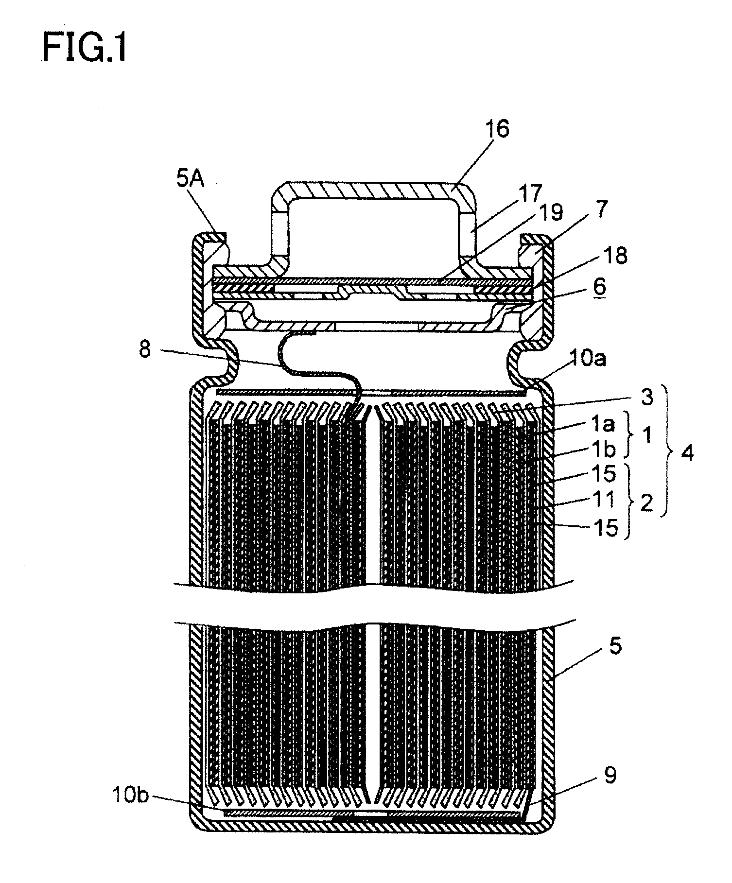
[0053]FIG. 1 is a cross-sectional view of a battery included in a battery module in a first embodiment of the present invention.
[0054]As illustrated in FIG. 1, the battery in a cylindrical shape includes an electrode group 4 in which a positive electrode 1 and a negative electrode 2 are wound with a separator 3 interposed therebetween. The positive electrode 1 includes a positive electrode lead 8 made of, for example, aluminum. The negative electrode 2 faces the positive electrode 1. One end of the negative electrode 2 is provided with a negative electrode lead 9 made of, for example, copper. Insulating plates 10a, 10b are installed above and below the electrode group 4, and the electrode group 4 with the insulating plates 10a, 10b is inserted in a battery case 5. The other end of the positive electrode lead 8 is welded to a sealing plate 6. The other end of the negative electrode lead 9 is welded to a bottom of the battery case 5. A nonaqueous electrolyte (not shown) capable of con...
second embodiment
[0086]FIG. 11 is a cross-sectional view of a battery included in a battery module of a second embodiment of the present invention.
[0087]As illustrated in FIG. 11, the battery module of the present embodiment is different from the battery module of the first embodiment in that an upper surface of a positive electrode cap 16 serving as an electrode portion of the battery is provided with an opening portion 77. Note that components other than batteries are the same as those of the first embodiment, and thus the description thereof may be omitted.
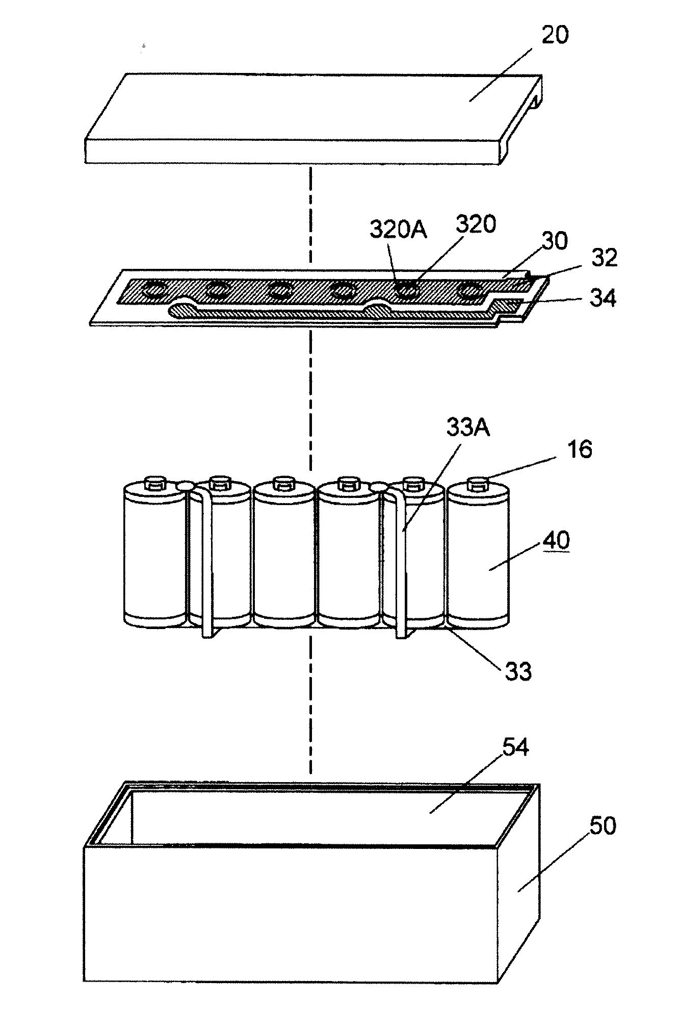
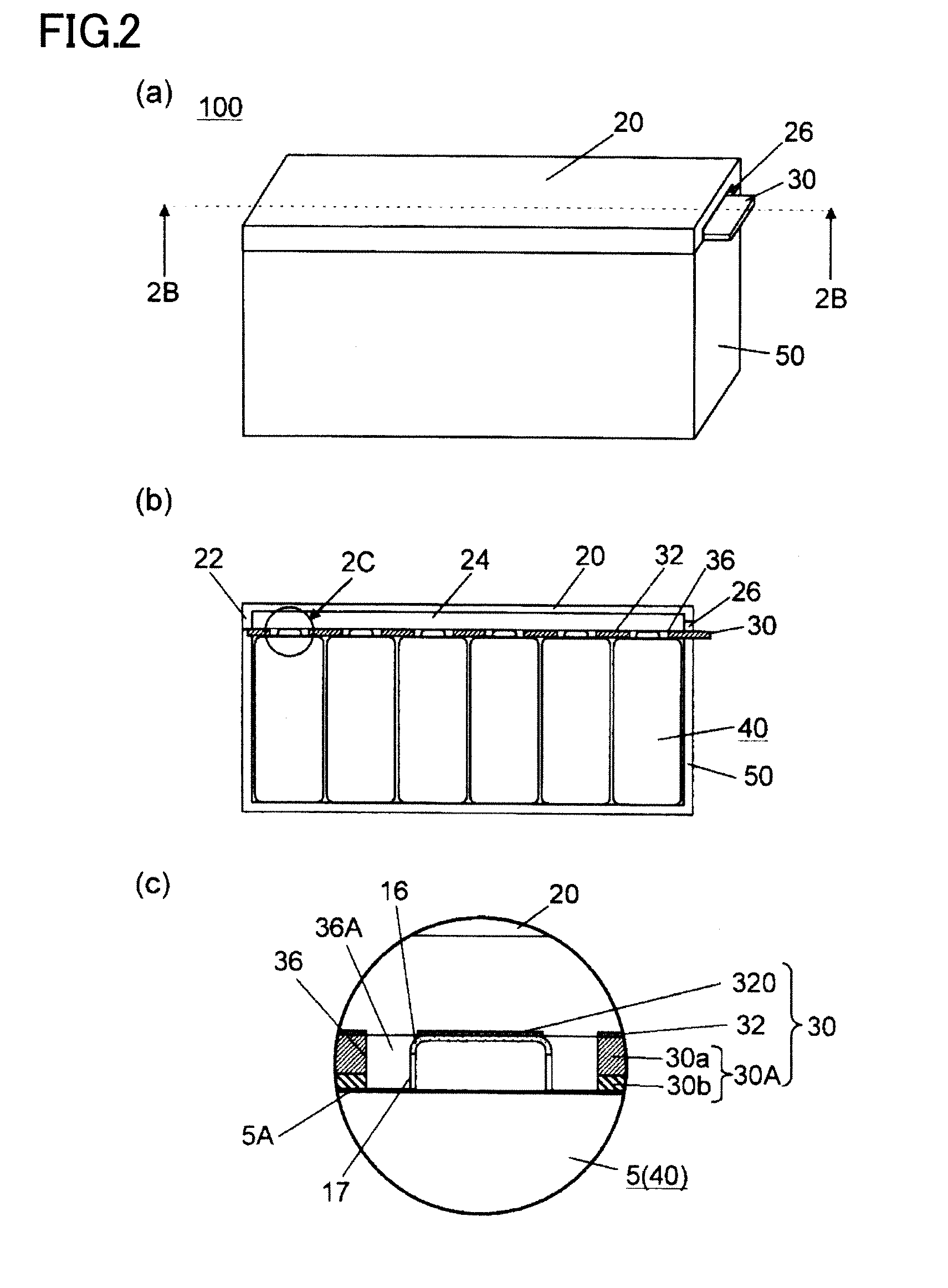
[0088]The battery module including the batteries of the present embodiment will be described in detail below with reference to FIGS. 12A-12C, and 13.
[0089]FIG. 12A is a perspective view illustrating the exterior of the battery module of the second embodiment of the present invention. FIG. 12B is a cross-sectional view along the line 12B-12B of FIG. 12A. FIG. 12C is an enlarged cross-sectional view of the part 12C of FIG. 12B. FIG. 13 is an expl...
third embodiment
[0099]A battery pack of the third embodiment of the present invention will be described in detail below with reference to FIGS. 16A and 16B.
[0100]FIGS. 16A and 16B are assembled perspective views of the battery pack of the third embodiment of the present invention.
[0101]In FIG. 16A, four battery modules of the above embodiments are arranged in parallel, and are connected by a connection member 450, thereby forming a battery pack 400. Alternatively, in FIG. 16B, battery modules of the above embodiments are parallelly arranged in pairs, the obtained two pairs of the battery modules are stacked in two tiers in the vertical direction, and are connected by a connection member 550, thereby forming a battery pack 500. Here, the battery modules are connected by the connection member, in parallel, in series, or in parallel and in series, thereby forming the battery pack.
[0102]According to the present embodiment, highly versatile battery packs having a required voltage and electric capacity c...
PUM
 Abstract
Description
Claims
Application Information
 - R&D
- Intellectual Property
- Life Sciences
- Materials
- Tech Scout
- Unparalleled Data Quality
- Higher Quality Content
- 60% Fewer Hallucinations
Browse by: Latest US Patents, China's latest patents, Technical Efficacy Thesaurus, Application Domain, Technology Topic, Popular Technical Reports.
© 2025 PatSnap. All rights reserved.Legal|Privacy policy|Modern Slavery Act Transparency Statement|Sitemap|About US| Contact US: help@patsnap.com


