
Photo-patterned pre-tilt liquid crystal cells, lenses and methods

a liquid crystal cell, pre-tilt technology, applied in the direction of hollow non-inflatable balls, instruments, lamination ancillary operations, etc., can solve the problem of large and achieve the effect of reducing the number of lithographically etched transparent electrodes

Active Publication Date: 2011-07-14
CALIFORNIA STATE UNIV SACRAMENTO +1
View PDF8 Cites 20 Cited by
  • Summary
  • Abstract
  • Description
  • Claims
  • Application Information

AI Technical Summary

Benefits of technology

[0010]Still another object of the present invention is to provide a liquid crystal cell with a low concentration of curable monomer, preferably light-curable monomer that allows for fabrication of a polymer network which provides low light scattering comparable to a pure liquid crystal cell.
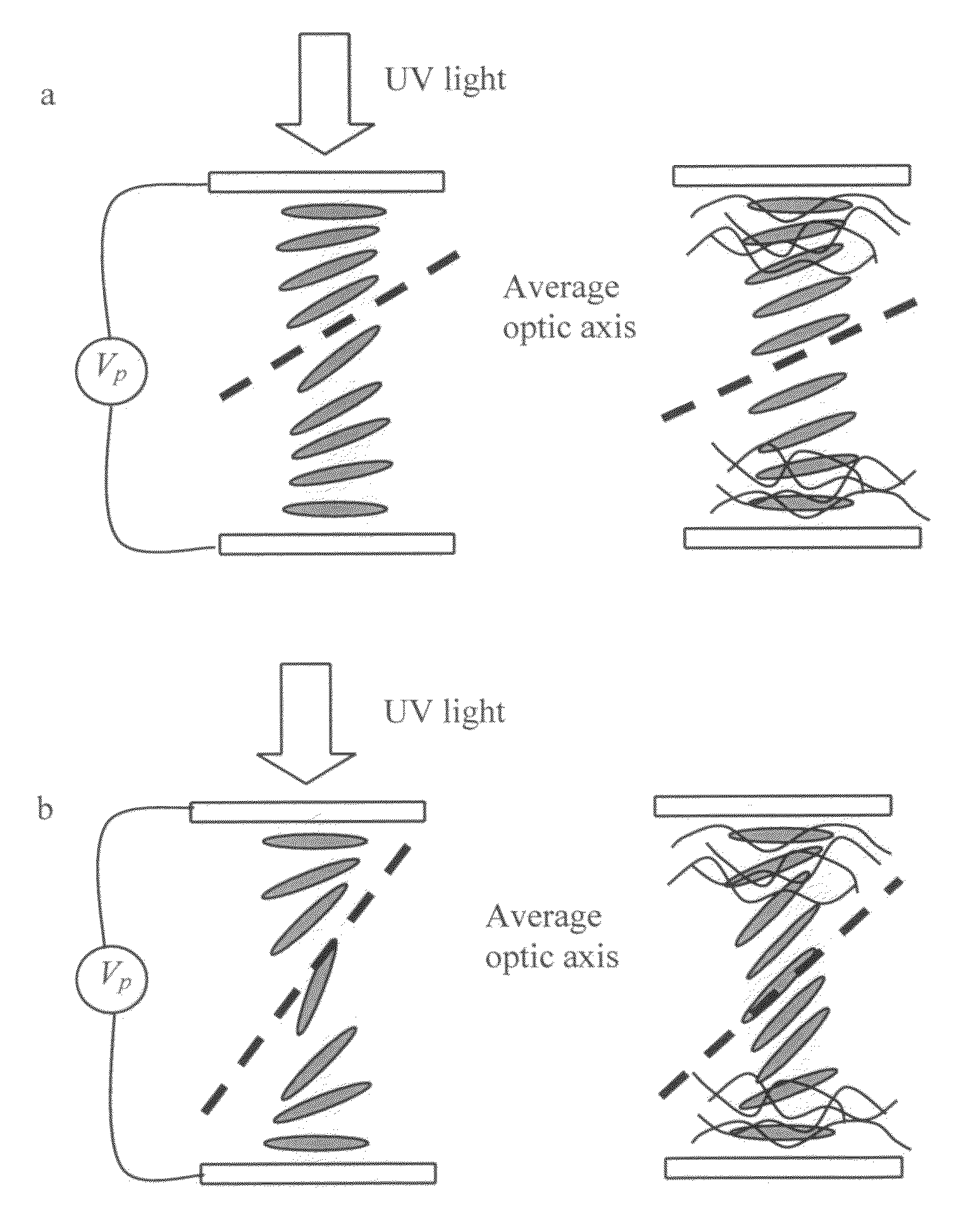
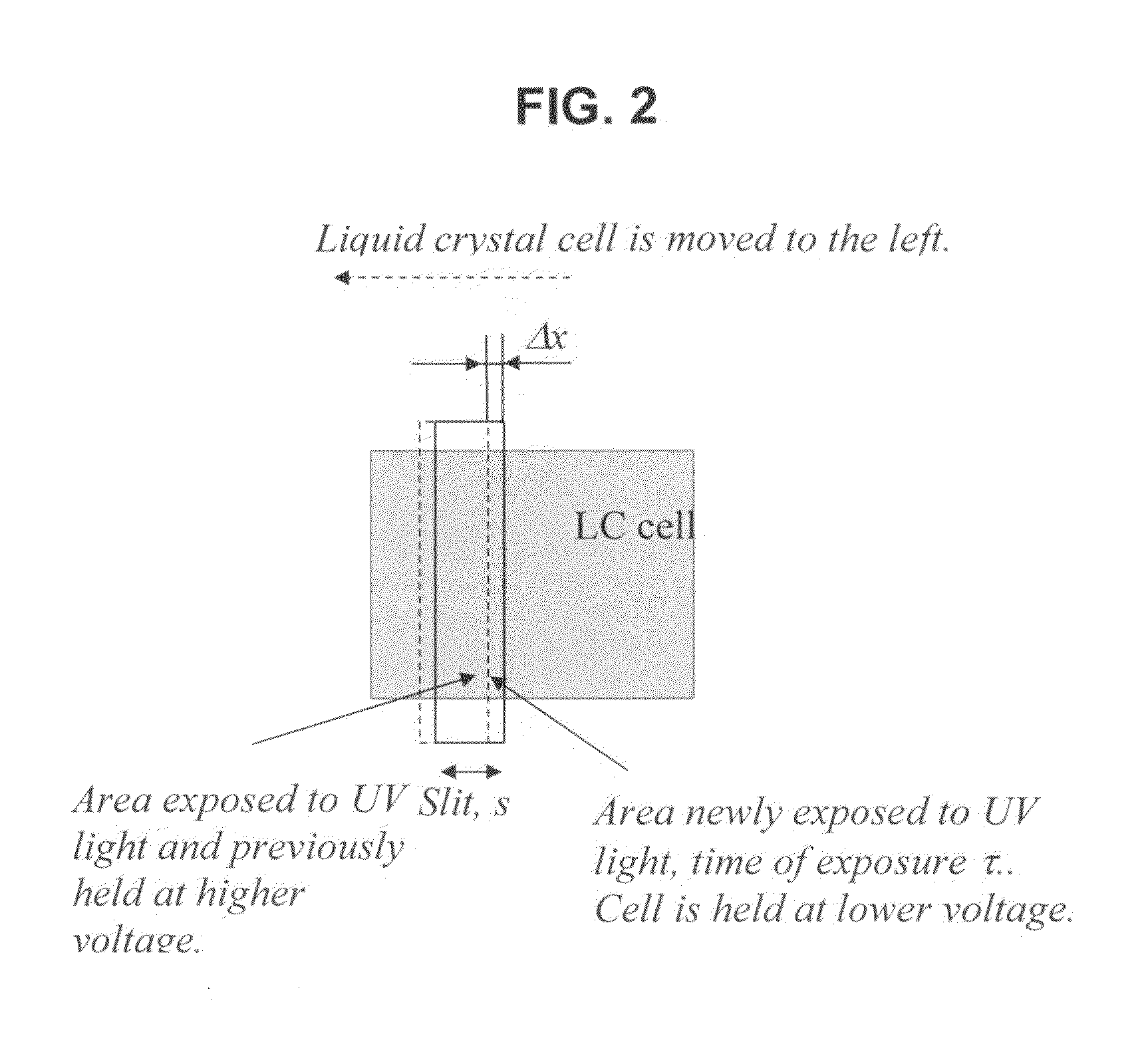
[0013]A further object of the present invention is to provide a liquid crystal cell or lens with a specified spatial distribution of the molecular pre-tilt angle of the liquid crystal near the cell substrate made possible by providing a multiple-step process of monomer polymerization of the cell by irradiating portions of the cell using two or more different voltages resulting in the formation of structures with pre-tilt angles that vary across the cell.
[0016]In a further aspect of the present invention, a method for fabricating an electro-optic device is disclosed, comprising the steps of obtaining a liquid crystal cell comprising a first substrate, a second substrate, a liquid crystal material layer located between the substrates and comprising liquid crystal material and a plurality of polymerizable monomers in an amount from about 0.01 to about 2 parts per 100 parts by weight of the liquid crystal material, and an electrode layer operatively connected to each substrate; and applying first a voltage to the cell and simultaneously polymerizing at least two monomers in a first area of the cell to form a polymer network, causing the liquid crystal material in the first area to have a different resulting pre-tilt angle when compared to at least a second area of the cell.

Problems solved by technology

One drawback of many liquid crystal electro-optic lens designs is that a large number of lithographically etched transparent electrodes are often required to create the desired phase profile.

Method used


Image

  • Photo-patterned pre-tilt liquid crystal cells, lenses and methods
  • Photo-patterned pre-tilt liquid crystal cells, lenses and methods
  • Photo-patterned pre-tilt liquid crystal cells, lenses and methods

Examples


example 1

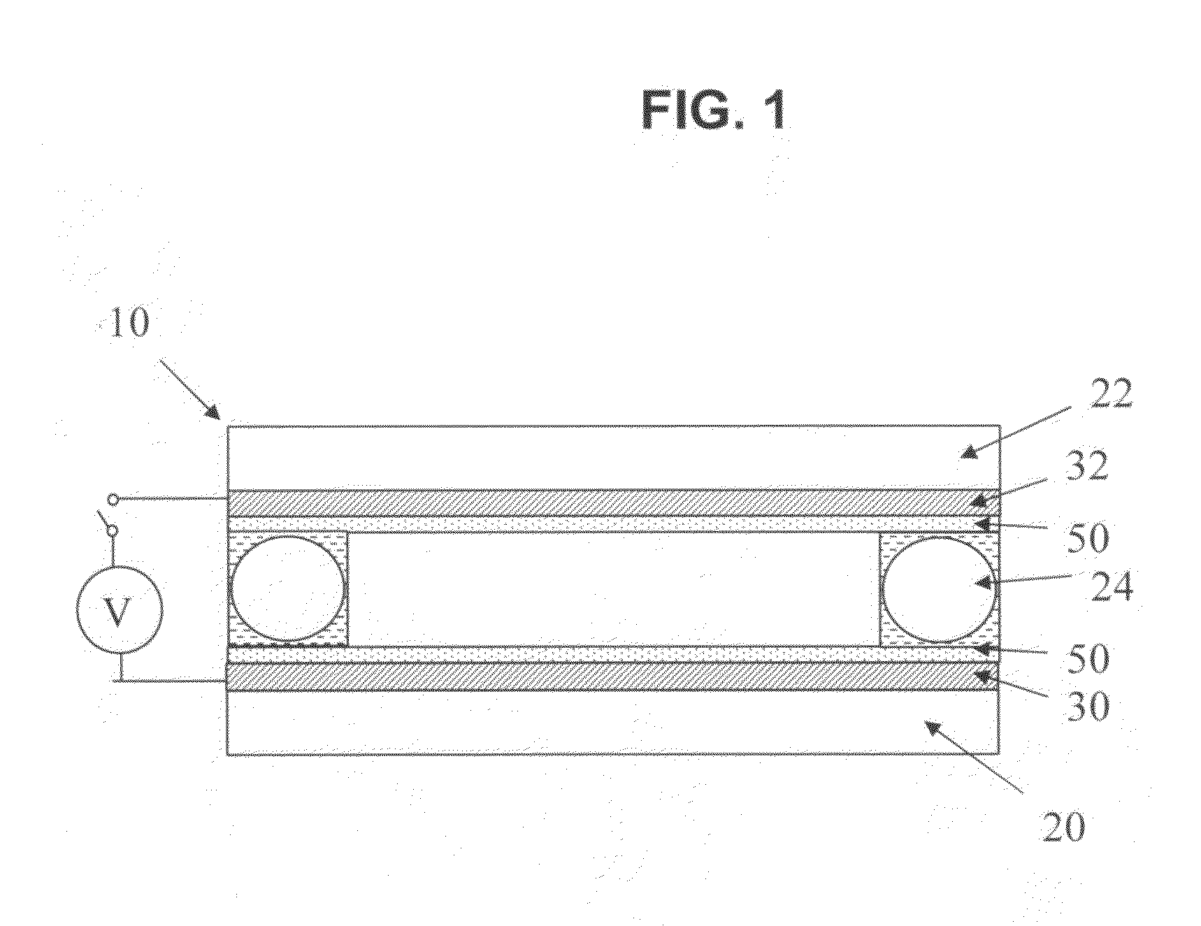
[0075]In this example, fabrication of uniform samples with a specified head-on optical retardation is shown, which is equivalent to increasing a pre-tilt angle. The liquid crystal cell is fabricated according to the cell fabrication procedure described. The cells have cell gaps of about d=20-21 μm. In this example, PI 2555 was used as an alignment layer. The cells were filled with a mixture of MLC 6080 (by EM Industries), about 0.5% BAB monomer and about 0.005% of Irgacure (by weight). The MLC 6080 material has the following characteristics:[0076]Refractive indices (at λ=589 nm): no=1.5076, ne=1.71, Δn=0.2024[0077]Dielectric constants: ∈parallel=11.1, ∈perpendicular=3.9, Δ∈=7.2.

The fluid demonstrated a pre-tilt angle of 2° on the polyimide alignment layer PI 2555 from DuPont.

[0078]The cells were irradiated with UV light from one cell side for about 30 minutes at the following power densities: 0.007 W / cm2 in UVA UVB (combined). AC voltage of 2, 10, 20, 30, 50, and 100 V rms of 200 Hz...

example 2

[0083]In this example, uniform samples with a specified pre-tilt angle were fabricated by building symmetric liquid crystal structures. This was achieved by illuminating the liquid crystal cells from two cell sides.

[0084]Liquid crystal cells were fabricated according to the procedure described earlier. The cells had a gap of d=20-21 μm and utilized KPI from IDW Company as an alignment layer. The cells were filled with mixtures of MLC 18349 from EM Industries, and 0.3, 0.5%, and 0.7% BAB monomer (by weight). The MLC 18349 has ne−no=Δn=0.26 and demonstrated a pre-tilt angle of about 3° on KPI. The cells were irradiated for about 20 minutes from two cell sides using two identical UV lamps facing each other, each having a UV power density of about 0.007 W / cm2 at each cell side. Irradiation from two cell sides was achieved by placing the UV lamps head-to-head on opposite cell sides. Resultant HOR, after the UV curing, was estimated according to the method described in Example 1. FIG. 9a-...

example 3

[0086]In this example, the director distribution was examined in the cells with anti-parallel rub (ECB cells) that had cell gaps of d=20.2±0.2 μm (measured when the cells were empty). The cells were filled with a mixture of MLC 6080 and 0.5% BAB monomer (by weight).[0087]MLC-6080[0088]Refractive indices (at λ=589 nm): no=1.5076, ne=1.71, Δn=0.2024[0089]Dielectric constants: ∈parallel=11.1, ∈perpendicular=3.9, Δ∈=7.2.[0090]Elastic constants: K11=14.4*10−12 J / m, K22=7.1*10−12 J / m, K33=19.1 / 10−12 J / m.[0091]Rotational viscosity: γ1=−α2=111 cp.[0092]The fluid demonstrates a pre-tilt angle of α=2-3.5° on the polyimide alignment layer PI 2555 (by Nissan Chemicals) (In modeling, α=3.5° was used).

[0093]The alignment layer used for fabrication of these cells was PI 2555 from DuPont. The cells were exposed to UV light by using two identical UV lamps (see description of the UV light source above). The cells were irradiated from two sides, with two light sources facing each other. Optical power ...


PUM

PropertyMeasurementUnit
Percent by massaaaaaaaaaa
Weightaaaaaaaaaa
Angleaaaaaaaaaa

Abstract

Liquid crystal cells and lenses having a variable resulting pre-tilt across two or more areas of the cell, and in particular, cells and lenses are provided wherein a resulting pre-tilt is varied across the cell according to any desired birefringence profile that can be utilized in liquid crystalline optical elements and liquid crystal displays. Methods of fabrication of the liquid crystal cells with variable resulting pre-tilt are disclosed.

Description

CROSS-REFERENCE[0001]This application claims the benefit of priority under 35 U.S.C. §119 of U.S. Provisional Application Ser. No. 61 / 275,962, filed on Sep. 4, 2009, herein fully incorporated by reference.STATEMENT OF GOVERNMENT INTEREST[0002]The U.S. Government has a paid-up license in the inventions and the right, in limited circumstances, to require the patent owner to license others on reasonable terms as provided for by terms of Contract Number FA 7014-07-C-0013 awarded by the U.S. Air Force.FIELD OF THE INVENTION[0003]The present invention relates to liquid crystal cells and lenses having a variable pre-tilt across two or more areas of the cell, and in particular, cells and lenses are provided wherein a resulting pre-tilt is varied across the cell according to any desired birefringence profile, and can be utilized in liquid crystalline optical elements and liquid crystal displays. Methods of fabrication of the liquid crystal cells and lenses with variable resulting pre-tilt ar...

Claims


Application Information

Patent Timeline
IPC IPC(8): G02F1/1334B32B37/14B32B38/00
CPCG02F1/133788G02F1/133753
Inventor BOS, PHILIPSERGAN, VASSILI V.SERGAN, TATIANA A.
Owner CALIFORNIA STATE UNIV SACRAMENTO
Learn More