Sound source estimation server, sound source estimation system, sound source estimation device, and sound source estimation method
- Summary
- Abstract
- Description
- Claims
- Application Information
AI Technical Summary
Benefits of technology
Problems solved by technology
Method used
Image

Examples
embodiment 1
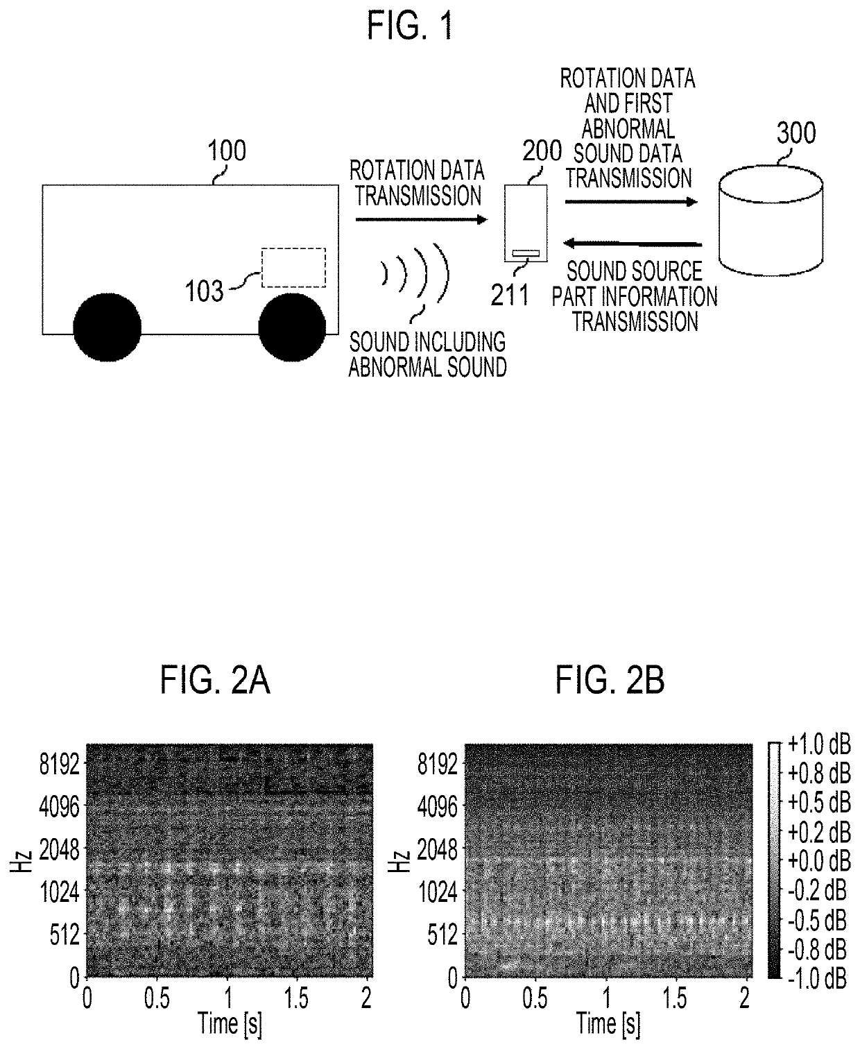
[0048]FIG. 1 is a diagram showing an outline of a vehicle 100, a portable terminal 200, and a server 300 that is a sound source estimation server according to Embodiment 1 of the present disclosure. In the present embodiment, the vehicle 100 is an object of sound source estimation.
[0049]The vehicle 100 includes an engine 103 that generates a rotary motion. In addition, a plurality of parts that moves in accordance with the rotary motion is mounted on the vehicle 100. Examples of the parts include a piston that reciprocates inside the engine 103, a camshaft that is rotated by power of the engine 103, an oil pump that is driven by the engine 103, and a plurality of gears that transmits the rotary motion generated from the engine 103. The parts generate an operation sound when moving in accordance with the rotary motion. However, in a case where any of the parts has abnormality, the vehicle 100 generates a sound (abnormal sound) different from an operation sound generated when the part...
embodiment 2
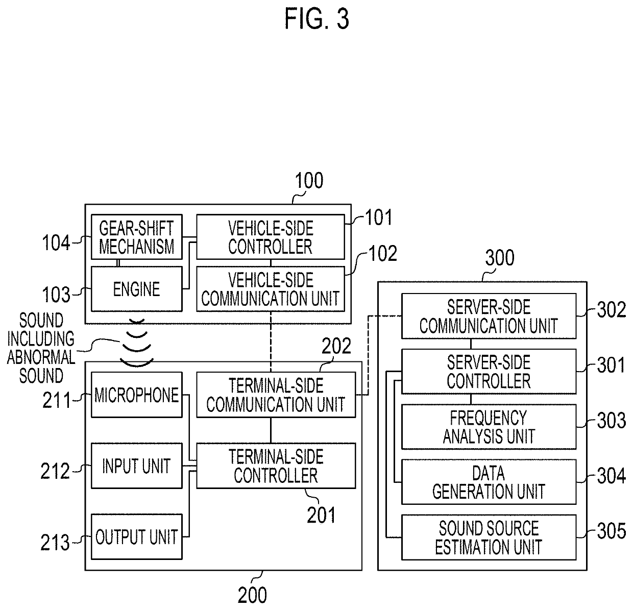
[0099]FIG. 9 is a diagram showing configurations of the vehicle 100, the portable terminal 200 provided with a sound source estimation system, and the server 300 according to Embodiment 2 of the present disclosure.
[0100]In the present embodiment, a frequency analysis unit 203 and a data generation unit 204 are provided in the portable terminal 200 instead of the server 300. The frequency analysis unit 203 and the data generation unit 204 are controlled by the terminal-side controller 201.
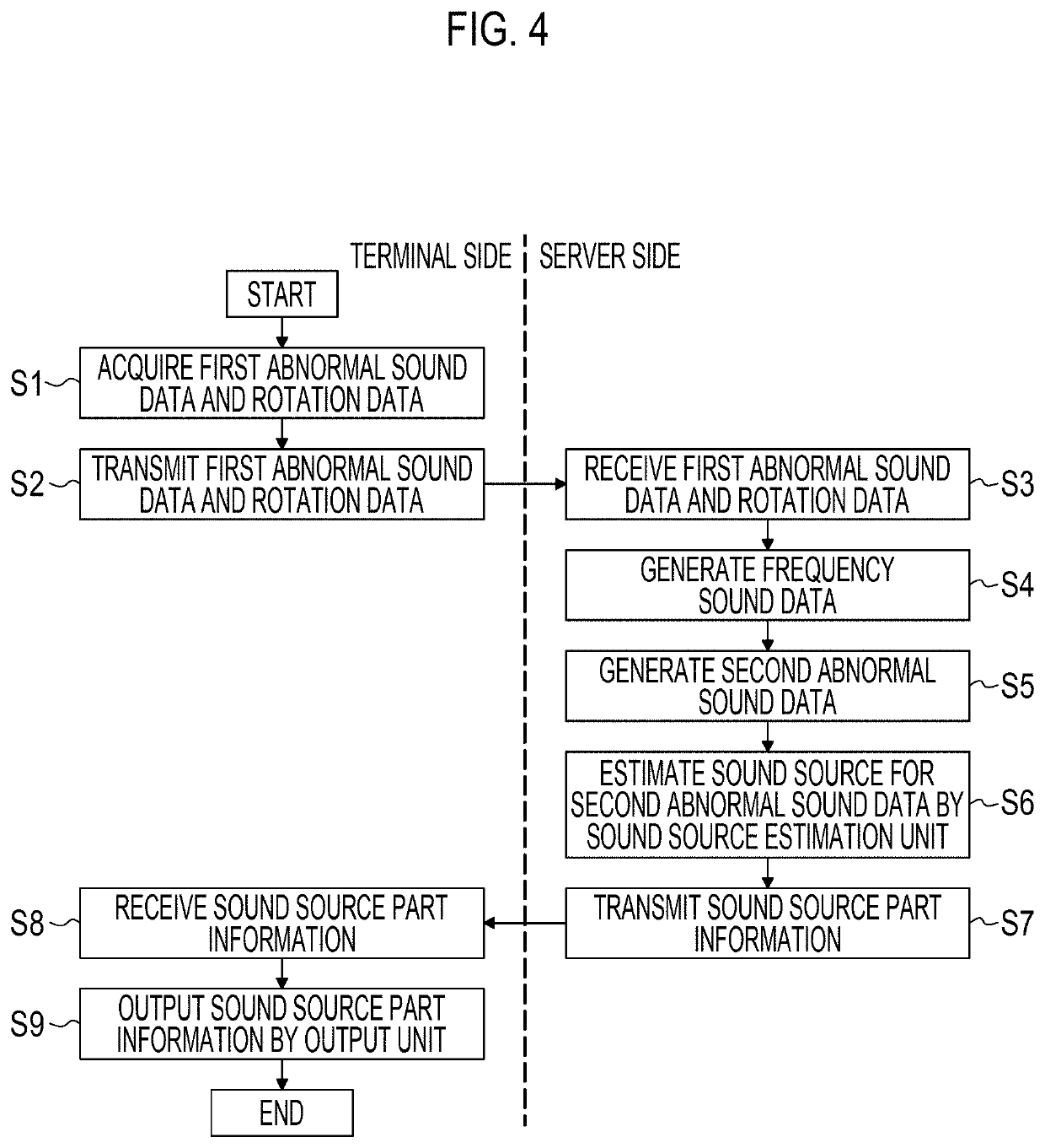
[0101]FIG. 10 is a flowchart showing a control flow of sound source estimation according to Embodiment 2.
[0102]The input unit 212 of the portable terminal 200 receives an operation relating to start of sound source estimation, thereby starting the present control. In S21, similarly to S1 of FIG. 4, the portable terminal 200 generates the first abnormal sound data from the sound including the abnormal sound detected by the microphone 211, and receives rotation data by using the terminal-side communic...
embodiment 3
[0109]FIG. 11 is a diagram showing configurations of the portable terminal 200 that is a sound source estimation device, and the vehicle 100 that is an object of sound source estimation according to Embodiment 3 of the present disclosure.
[0110]In the present embodiment, unlike Embodiment 1 and Embodiment 2, there is no server 300 for performing sound source estimation, and the portable terminal 200 includes the frequency analysis unit 203, the data generation unit 204, and a sound source estimation unit 205.
[0111]FIG. 12 is a flowchart showing a control flow of sound source estimation according to Embodiment 3.
[0112]The input unit 212 of the portable terminal 200 receives an operation relating to start of sound source estimation, thereby starting the present control. In S31, similarly to S1 of FIG. 4, the portable terminal 200 generates the first abnormal sound data from the sound including the abnormal sound detected by the microphone 211, and receives rotation data by using the te...
PUM
 Abstract
Description
Claims
Application Information
 - R&D
- Intellectual Property
- Life Sciences
- Materials
- Tech Scout
- Unparalleled Data Quality
- Higher Quality Content
- 60% Fewer Hallucinations
Browse by: Latest US Patents, China's latest patents, Technical Efficacy Thesaurus, Application Domain, Technology Topic, Popular Technical Reports.
© 2025 PatSnap. All rights reserved.Legal|Privacy policy|Modern Slavery Act Transparency Statement|Sitemap|About US| Contact US: help@patsnap.com