Liquid chromatograph

a liquid chromatograph and chromatograph technology, applied in the field of liquid chromatographs, can solve the problems of increasing tubing length and dead volume, decreasing separation performance of columns, so as to enhance analytical precision, reduce dead volume, and perform firm installation with ease

Inactive Publication Date: 2011-07-14
GL SCI
View PDF5 Cites 29 Cited by
  • Summary
  • Abstract
  • Description
  • Claims
  • Application Information

AI Technical Summary

Benefits of technology

[0016]The object of the present invention is to provide liquid chromatograph which is capable of solving the aforementioned problems and suitable for liquid chromatograph system (hereinafter referred to as LC system), and which has its constituent elements installed rationally, enables the lengths of tubing for connecting the respective constituent elements to be minimized, reduces the dead volume in the LC system lines, increases the analytical precision through the prevention of sample diffusion and rapid movement of a mixed solvent and, at the same time, sets analytical environment relative to the respective constituent elements rationally and suppresses influences resulting from fluctuation of the analytical environment to thereby enable the repeatability and reliability of the analytical results and enable the attachment, maintenance and inspection of the respective constituent elements to be performed with ease, while installing the flow cell including detection unit of a detector within an oven of constant temperature, suppressing the oven or LC system being large in size, simultaneously cleaning flow channels with cleaning liquid precisely and rationally, and preventing cross-contamination resulting from residues of the samples and cleaning liquid in the flow channels and, at the same time, isolating the area of movement of a needle during cleaning from a pool area of the samples and obviating contamination resulting from a fall of the samples and cleaning liquid having adhered to a needle, thereby enabling the analytical reliability.
[0017]The invention according to a first aspect thereof relates to a liquid chromatograph comprising a sample tray for storing thereon multiple sample bottles containing samples; an autosampler equipped with a needle that moves above the sample tray and is capable of sucking therein and discharging therefrom each of the samples; an injection piece having an injection port into which the needle is inserted; an oven having an interior adjustable in temperature to a prescribed temperature; and an injection valve which has a flow channel and into which a sample is loaded via the needle, a mixer capable of mixing plural elution solvents, a column which has an inlet and an outlet and is capable of separating a sample containing plural components and a detector capable of measuring the separated components, which are all disposed in the oven wherein the injection valve is disposed within the oven and above an upper side of the column. The mixer and the inlet of the column are placed closing to the injection valve, and the flow cell including detection unit is placed closing to the exit side of the column. the injection port is disposed on one side of the autosampler and connected with the injection valve to enable the injection port to connection with the flow channel of the injection valve. The injection valve and injection port are allowed to connection with each other in the smallest length, so that any connection tubing between them can be omitted, and each of connection tubing between the injection valve and the mixer, between the injection valve and the inlet of the column and between the outlet of the column and the flow cell including detection unit of the detector is plumbed in the shortest length to reduce a dead volume in each connection. By suppressing the diffusion of the sample and obtaining the concentration gradient relative to the flow direction of a mobile phase correctly, the analytical precision can be enhanced. The injection valve, mixer, column and flow cell including detection unit are set in the same analytical environment to suppress the influence caused by a change in temperature and obtain analytical reliability. By improvement of the maintenance of the constituent elements and installing the flow cell including detection unit within the oven, it is possible to prevent the size enlargement of the oven and the variation and distribution of temperature, suppress the size enlargement of the LC system and realize safety and reliability of the samples injected by the needle via the injection port.
[0018]The invention according to a second aspect thereof relates to the liquid chromatograph, wherein the detection portion of the detector is installed at a position which is close to the column and which is movable and adjustable so as to be corresponding to a position of the column. As a result, it is possible to compactly dispose the detection portion rationally, realize the shortest plumbing of the tubing for connection between the column and the detection portion and reduce the dead volume in the tubing. The invention according to a third aspect thereof relates to the liquid chromatograph, wherein the column is installed at a position movable and adjustable in a three-dimensional direction relative to the injection valve or switching valve and the detection portion of the detector. As a result, it is possible to compactly dispose the column and injection valve or the switching valve and detection portion of the detector rationally, realize the shortest plumbing of the tubing for connection between them and reduce the dead volume in the tubing.

Problems solved by technology

Generally, the components (units) are independently piled up and, therefore, their connection is irrational and leads to increase in tubing length and dead volume and decrease in separation performance of the column.
In the LC systems of this kind, since the constituent elements have generally been prioritized in their respective functions and disposed independently of one another, tubes for connecting the elements have lacked in rationality, the tubes for the respective elements have become long to increase the dead volume, the separation performance of the column has not been fulfilled, the enhancement of the analytical performance has not been attained and, moreover, it has been irrational that the countermeasures against analytical environment including temperature management for the respective elements have had to be individually taken.
In addition, when it has been required to select and alter the detector in accordance with conditions of analysis of the sample, such problems as necessitating addition and exchange of a single item of device have been entailed.
However, the above device has restrictions on the position of the valve head in the oven, and hence had a limitation in shortening the tubing length for connecting the column and injection valve, and there have been limitations to reduction of the dead volume in that portion.
In addition, since the detector is disposed outside the oven, this fact has entailed problems of elongating the tubing length and increasing the dead volume in that portion.
Furthermore, since the gradient mixer built in the oven and the injection valve or column are disposed apart from each other, this leads to the possibility of gradient delay and the difference from the gradient program.
Moreover, since the injection valve is disposed between the autosampler and the oven, this results in many problems with the disposition and positioning of the autosampler and the oven as well as the maintenance and inspection of the injection valve.
However, the above device has entailed problems of taking a sufficient length of the tubing for connecting the injector and the column because the injector is moved in association with the opening / closing operation of the sub-door; this increased dead volume of the connection tubing degree of the sample diffusion.
In addition, since the housing has accommodated therein the oven unit that is an element required for the analysis, this fact has entailed problems of making the housing large and heavy, carrying and installing the housing with difficulty and inconvenient maintenance of the column or detector within the oven unit.
However, the above device has entailed problems of requiring a wide storing space because the plural measurement units are stored in the temperature adjustment box to enlarge the size and weight of the device, increasing the analysis cost because of a large heat load and making the maintenance of the measurement units inconvenient.
In the method for cleaning the inside and outside the needle, however, since the needle completed sample injection therein that has been moved to the cleaning port and moved from the cleaning port into the second cleaning liquid is again moved to the cleaning port, the cleaning process is cumbersome and requires great care, and its operation control becomes complicated.
Furthermore, since a cleaning liquid bottle is disposed near a sample bottle, the sample or cleaning liquid having adhered to the needle drops onto the sample bottle or cleaning liquid bottle during movement of the needle to foul the neighborhood of the needle-moving region and, at the same time, incur cross-contamination, thereby lowering the reliability of the analysis.
This has been problematic.
However, the method for cleaning the inside and outside the needle has entailed problems of requiring the needle completed sample injection therein to move to the cleaning port, making the cleaning process cumbersome and requiring great care relative to the cleaning process, making its operation control complicated and, at the same time, allowing the sample or cleaning liquid having attached to the needle to drop onto the sample bottle during the movement of the sample because the cleaning port is disposed near the sample bottle, thereby fouling the neighborhood of the needle-moving region and incurring cross-contamination to thereby lowering the reliability of the analysis and also allowing droplets of the cleaning liquid to fly in all directions from the spray nozzle to foul the neighborhood of the cleaning port and deteriorating the analytical environment.

Method used


Image

  • Liquid chromatograph
  • Liquid chromatograph
  • Liquid chromatograph

Examples


second embodiment

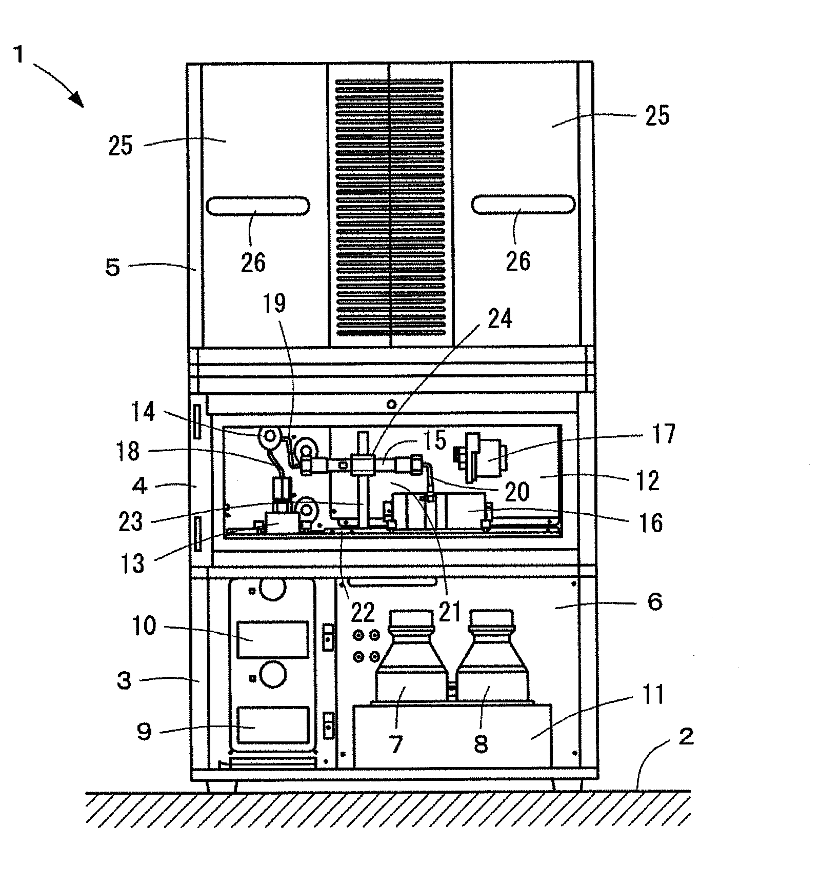
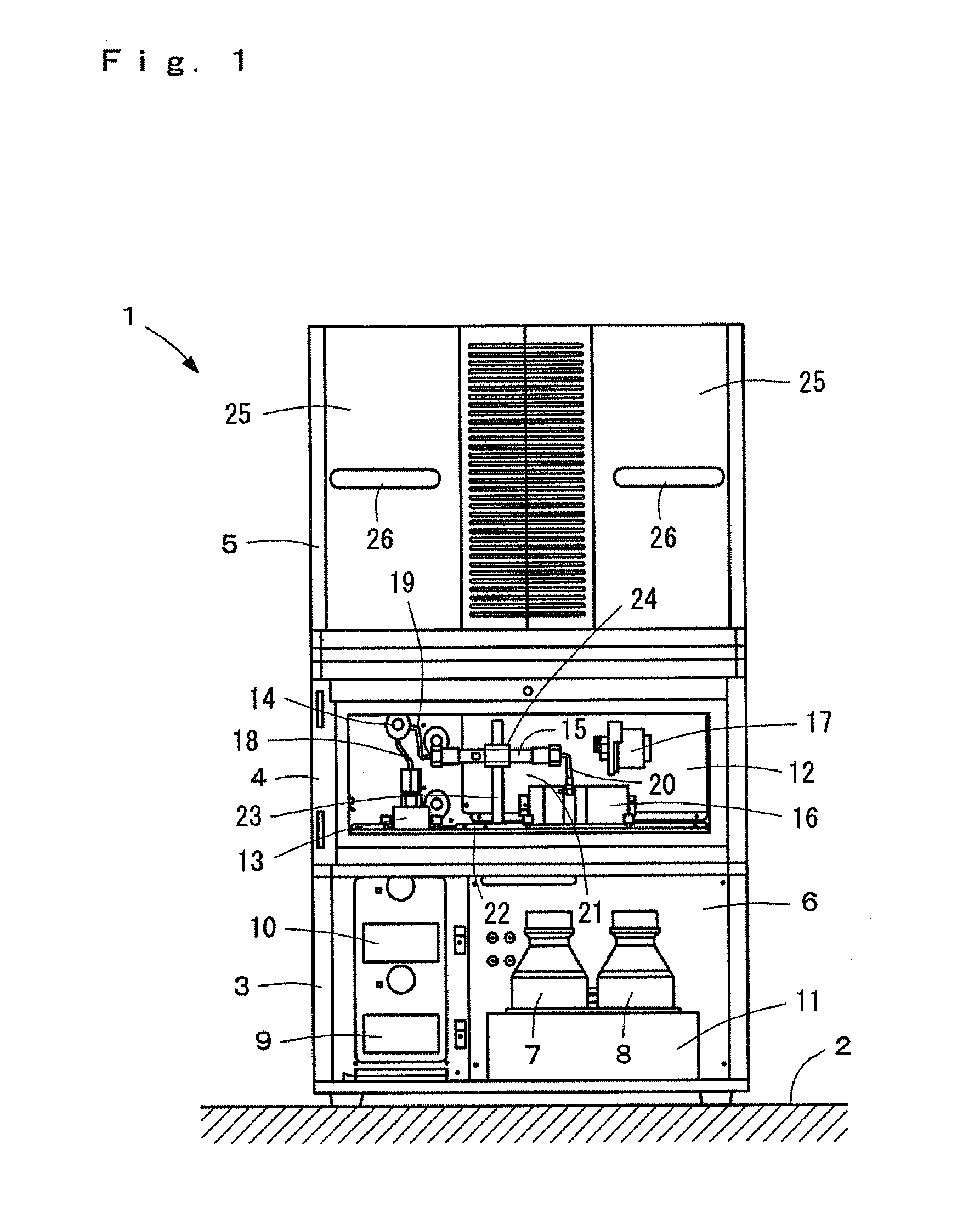
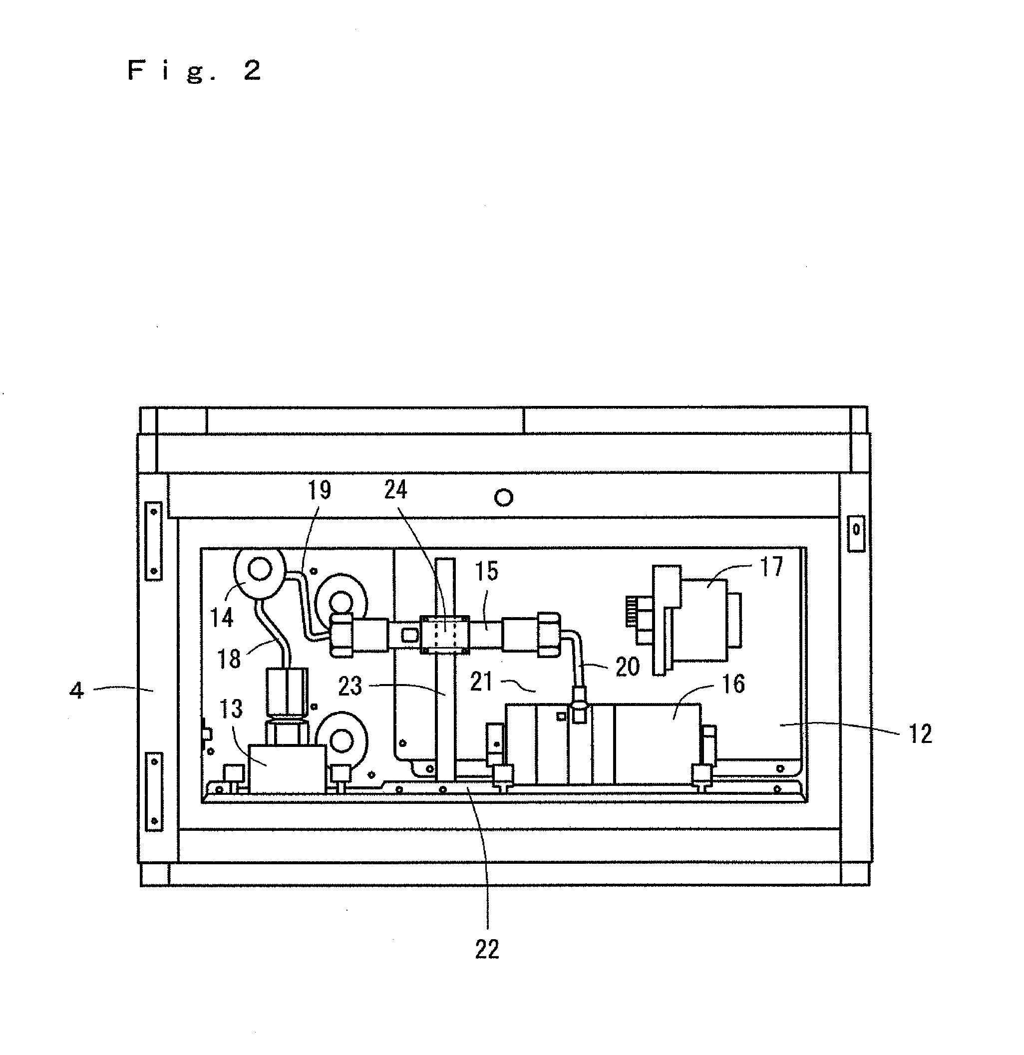
[0152]FIG. 12 to FIG. 14 show different embodiments of the present invention, in which the constituent elements corresponding to those of the previous embodiment are given the same reference numerals. Of these embodiments, FIG. 12 and FIG. 13 show the present invention, illustrating a case where the present invention has been applied to an LC system for a high-performance liquid chromatograph provided with a column switching function. That is to say, the oven 12 has the mixer 13, the injection valve 14, the main column 15 for analysis, the detection portion 16 or 17, such as a UV-VIS detector or an electrochemical detector, a switching valve 85 and a trap column 86 disposed therein capable of being set to the same analytical environment or the same temperature conditions.

[0153]The switching valve 85 comprises a six-port changeover valve and is formed therein with six loop flow channels that can selectively be switched between the flow channels shown by solid lines in FIG. 12 and the...

third embodiment

[0166]In the third embodiment thus configured, since the mixers 13 and 102, injection valve 14, separation columns 15 and 99, trap column 86, switching valves 85 and 96 and detection portion 16 or 17 are disposed inside the oven and since their connection tubing 89, 90 and 97 can be plumbed in their shortest lengths, the dead volumes therein can be reduced, the solvent can rapidly be sent to obtain the constituent elements exhibiting sharper peaks without being influenced by room temperature and obtain stable repeatability.

[0167]In this embodiment, the sample introduced from the injection valve 14 is moved to the switching valve 96 together with the eluting solution produced via the mixer 102 from the one-dimensional liquid-sending pumps 100 and 101 and, by stepwise changing the composition ratio using the liquid-sending pumps 100 and 101, separated by the one-dimensional separation column 99. The component of the sample eluted is guided by the tubing 97, moved to the switching valv...


PUM


Abstract

A liquid chromatograph provided here is adapted to enable the lengths of tubing for connecting the respective constituent elements thereof to be minimized by making the positions of the respective constituent elements including a detector and a column movable and adjustable in order to reduce the dead volume in a liquid chromatograph system in plumbing and increase the analytical precision through prevention of diffusion of samples and rapid sending of a mixed liquid solvent. Furthermore, in order to prevent cross-contamination due to residues of samples and cleaning liquid in a flow channel of the liquid chromatograph system, an injection port in which a needle can be inserted is so provided as to communicate directly with a flow channel of an injection valve.

Description

BACKGROUND OF THE INVENTION[0001]The present invention relates to liquid chromatograph (hereinafter referred to as LC system) and related systems. In the system, each component is rationally arranged and connected in the shortest distance to reduce system dead volume including tubing, and prevent diffusion of the sample. While rapid mixed solvent delivery results in the improvement of analytical accuracy, each components which is sensitive to change in ambient temperature can be installed in a suitable environment where the effect of change in environmental conditions on analytical results is reduced and controlled to achieve high reproducibility and reliability. The attachment and maintenance of each components can be easily performed, and only detection unit of the detectors built in an oven to keep its stability and avoid large size of the oven and the LC system. The lines of the sample and the flushing solvent can be rationally arranged, and completely flushed with suitable solv...

Claims


Application Information

Patent Timeline
IPC IPC(8): G01N30/20
CPCG01N30/6047G01N30/24
Inventor ZHOU, XIAOJINGUZU, HIDEYUKI
Owner GL SCI
Why Eureka
Try Eureka