Energy recovering system for an internal combustion engine

a technology of energy recovery and internal combustion engine, which is applied in the direction of engines, machines/engines, mechanical equipment, etc., can solve the problems of unrecoverable additional heat or energy sources, unusable energy content of known engines, and worse global energy balance, etc., to achieve the effect of reducing backpressure on the main exhaust line, reducing thickness, and reducing volum

Inactive Publication Date: 2011-07-14
RENAULT TRUCKS
View PDF25 Cites 5 Cited by
  • Summary
  • Abstract
  • Description
  • Claims
  • Application Information

AI Technical Summary

Benefits of technology

[0008]It is also desirable to provide an energy recovering system for an engine arrangement comprising an internal combustion engine which better uses the energy contained in the exhaust gas.
[0031]In an advantageous way, the heat exchanger is located, on the exhaust line, downstream from the main filter, so that the heat exchanger is protected against clogging by the filter.

Problems solved by technology

However, generally, these systems are capable to use only one of the aforesaid energy sources.
Moreover, they can generate undesirable side-effects, such as increased backpressure in the exhaust line, which are prejudicial to the global engine efficiency.
As a result, known engines dissipate uselessly the energy content of the particles.
Moreover, the additional heat or energy source is not recovered, which makes the global energy balance even worse.

Method used


Image

  • Energy recovering system for an internal combustion engine
  • Energy recovering system for an internal combustion engine

Examples


Embodiment Construction

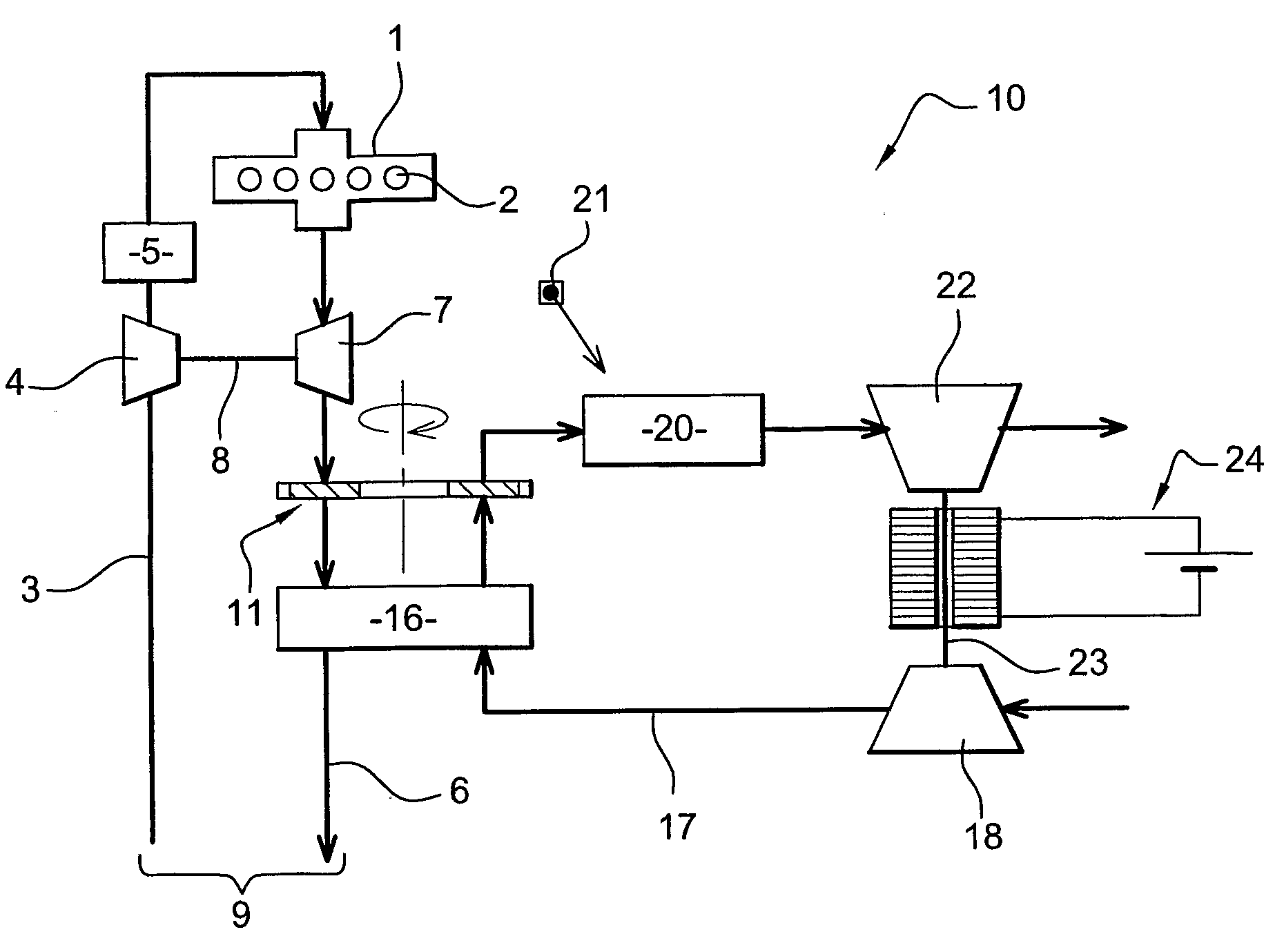
[0040]As depicted in FIG. 1, an internal combustion engine typically comprises an engine block 1 defining a plurality of cylinders 2, namely six cylinders in the illustrated embodiment. The engine is for example a diesel engine. However the invention may concern any type of internal combustion engine needing a particle filter to meet ongoing or future legislation limits.

[0041]Intake air is carried towards an intake manifold feeding the cylinders 2 through an air intake line 3. Air intake line 3 can include a compressor 4 and an air intake cooler 5 located downstream from said compressor 4.

[0042]Exhaust gas formed in each cylinder 2 is collected by an exhaust manifold and then carried through an exhaust line 6 towards the atmosphere. The exhaust line 6 can suitably comprise a turbine 7 driven by the exhaust gas, said turbine 7 being mechanically connected to compressor 4 by means of a shaft 8.

[0043]Intake line 3 and exhaust line 6 define a main line 9 of an energy recovering system 1...


PUM


Abstract

An engine arrangement including an internal combustion engine and an energy recovering system includes an exhaust line collecting exhaust gas from the engine,a filter having an active portion inserted between two successive parts of the exhaust line, in order to hold the particles contained in the exhaust gas, and filter rotating means designed to rotate the filter so as to shift the active portion of the filter,a secondary line carrying intake air towards an area of said filter distinct from the active portion, according to a direction opposite from an exhaust gas flowing direction inside the filter, so as to sweep the particles away from the filter and release them downstream, inside the secondary line. The secondary line includes a first arrangement, located downstream from the filter, for burning the particles and thereby heating air flowing in the secondary line, and a second arrangement capable of recovering the heat into work.

Description

BACKGROUND AND SUMMARY[0001]The present invention relates to an engine arrangement, for example for an automotive vehicle, especially an industrial vehicle. More specifically, the invention relates to an energy recovering system for such an engine arrangement.[0002]For many years, attempts have been made to improve vehicle efficiency, and more particularly the engine arrangement efficiency, which has a direct impact on fuel consumption.[0003]A significant amount of energy is included in the exhaust gases which have a high speed, a high temperature, and which, especially in the case of diesel engines, contain particles resulting from an incomplete combustion process in the engine.[0004]Several systems have been designed to recover at least part of this energy. However, generally, these systems are capable to use only one of the aforesaid energy sources. Moreover, they can generate undesirable side-effects, such as increased backpressure in the exhaust line, which are prejudicial to t...

Claims


Application Information

Patent Timeline
Patent Type & Authority Applications(United States)
IPC IPC(8): F01N3/023
CPCF01N3/0214F01N3/023F01N3/0233Y02T10/166F02G5/02Y02T10/16F01N5/02Y02T10/12
Inventor BALLOUL, IYADVANVOLSEM, MICHELLEJEUNE, MARC
Owner RENAULT TRUCKS
Why Eureka
Try Eureka