
Method for transmitting a digital signal between at least two transmitters and at least one receiver, using at least one relay, and corresponding program product and relay device

a digital signal and relay technology, applied in the direction of digital transmission, code conversion, code conversion, etc., can solve the problems of increasing transmission time, little compatibility with real-time applications, and relative mediocrity of transmission reliability, so as to reduce the number of relay errors, reduce the number of mean square errors, and improve efficiency

Active Publication Date: 2011-06-30
FRANCE TELECOM SA +1
View PDF0 Cites 12 Cited by
  • Summary
  • Abstract
  • Description
  • Claims
  • Application Information

AI Technical Summary

Benefits of technology

[0017]a second step for sending said second code word or code words by means of said relay device or devices,so as to make it possible, in said receiver or receivers, to carry out an iterative decoding taking account of said first code words and then a redundancy formed by said second code word or code words.
[0045]In other words, it is possible to cascade relay devices. More generally, it is possible to envisage many arrangements, if necessary variable in time and / or in space, for combining the transmitters and the relays so as to improve the quality of the decoding.

Problems solved by technology

Unlike in a landline network, the transmission channel of a wireless network or mobile network is reputed to be difficult and leads to relatively mediocre reliability of transmission.
Its main defect is that it increases the transmission time and therefore has little compatibility with real-time applications (telephony for example).
Furthermore, new emerging applications such as sensor networks or also the broadcasting of television signals to mobile units are subject towards constraints of complexity and / or consumption that are incompatible with these solutions.
This solution has several defects: it is highly sensitive to errors in the relay and above all the analog value of the LLR must be transmitted with sufficient precision (four bits at least) between the relay and the receiver for each bit of the stream sent by the sources, and this is to the detriment of the capacity of the network.
In these different cases, the decoding is difficult and there is no simple and efficient solution for processing in the receivers.

Method used

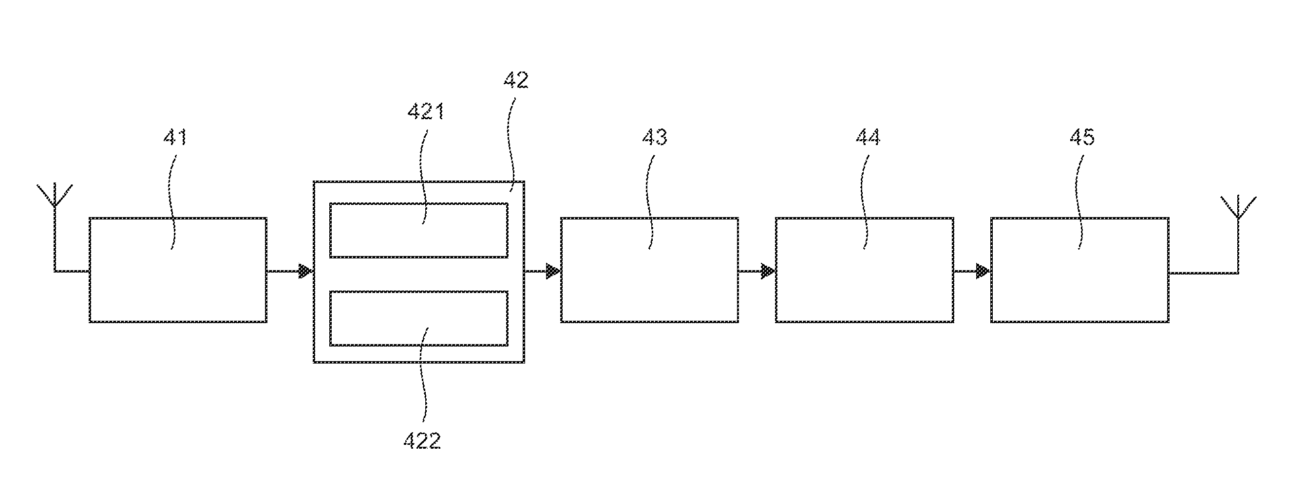

Image

  • Method for transmitting a digital signal between at least two transmitters and at least one receiver, using at least one relay, and corresponding program product and relay device
  • Method for transmitting a digital signal between at least two transmitters and at least one receiver, using at least one relay, and corresponding program product and relay device
  • Method for transmitting a digital signal between at least two transmitters and at least one receiver, using at least one relay, and corresponding program product and relay device

Examples


first embodiment

2. First Embodiment

[0078]2.1 Principle

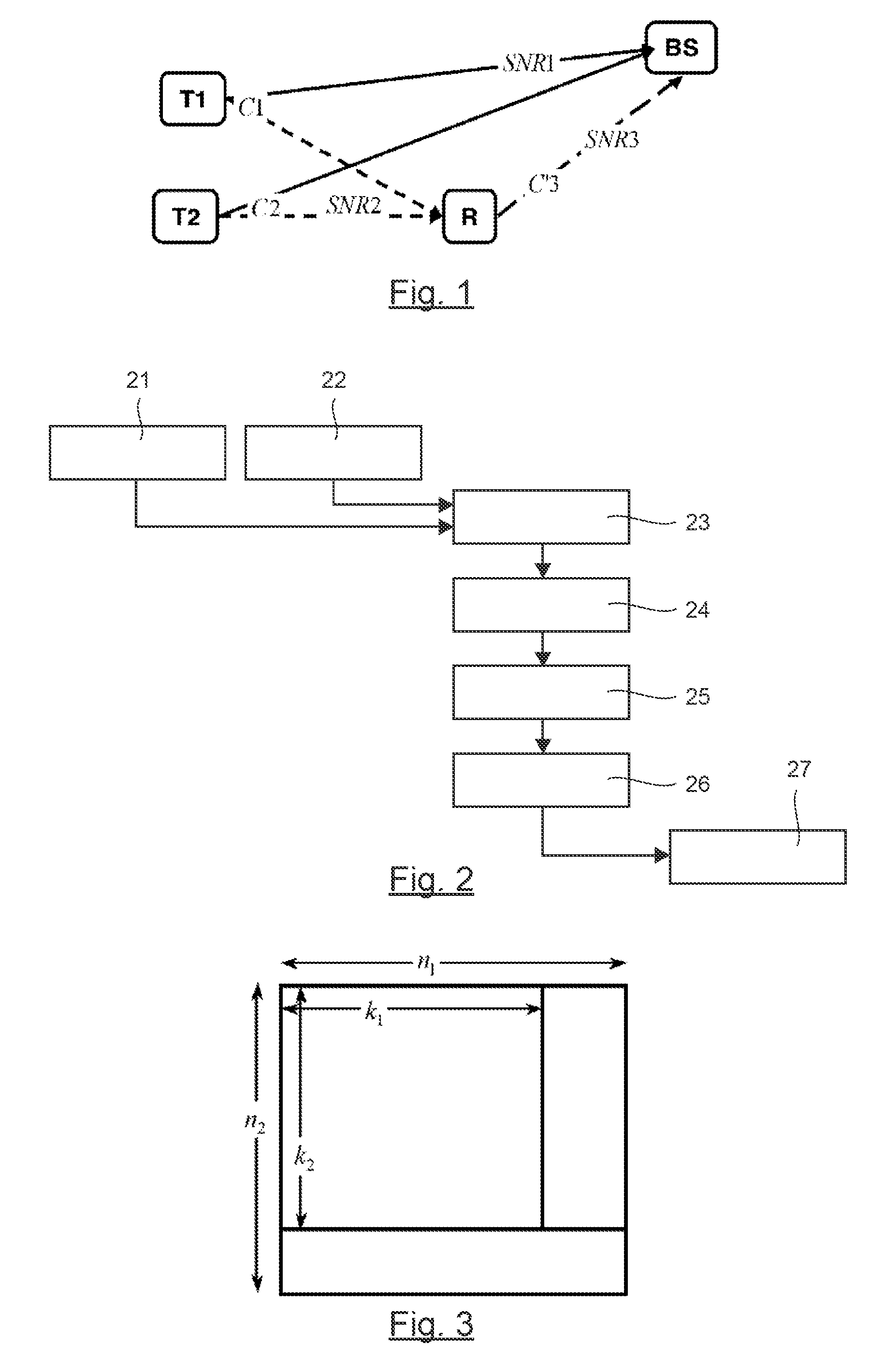
[0079]In the case of a simple transmission system illustrated by FIG. 1, implementing two transmitters T1, T2 one relay R and one receiver BS (in the example implemented, a base station), the relay receives C1 and C2 and delivers the sequence C′3.

[0080]The base station therefore has available three code words or sequences C1, C2 and C′3, which it can decode according to an iterative decoding method.

[0081]The method implemented is illustrated in simplified form in FIG. 2.

[0082]Each transmitter sends (21, 22) one code word C1, C2. Depending on the embodiments, it is of course possible to make the transmitters send several code words simultaneously, if necessary at different bit rates and / or variably in time. Again, in this case, an adapted signaling is preferably implemented.

[0083]The relay receives (23) these code words and applies a bit-by-bit thresholding of the observations to give C′1 and C′2. It can be noted that C′1 and C′2 are not inevitab...

second embodiment

3. Second Embodiment

[0114]FIG. 5 illustrates an example of implementation of an embodiment of the invention with four transmitters, one relay and one receiver. FIG. 6A to 6D present the results of simulation obtained for a system of this kind

[0115]We therefore consider the case where four terminals T1, T2, T3 and T4 are sending to a base station BS (receiver as understood in the claims) using a relay R. The terminals send code words of a BCH code (64, 51, 6) and the relay R makes a linear combination of the four received code words C1 to C4, and sends a fifth code word C′5 in the same way as indicated here above.

[0116]The base station performs an iterative decoding of the corresponding product code (BCH (64, 51, 6)*parity (5, 4, 2)), which has a minimum distance of 12.

[0117]The signal-to-noise ration SNRi is defined as the energy per bit received (data bit or parity bit) divided by the power spectrum of the single sideband noise. SNR1 corresponds to the link between a terminal and t...


PUM


Abstract

A method is provided for transmitting a digital signal between at least two transmitters and at least one receiver, using a concatenation of at least two codes. The method includes a first encoding step, in the transmitters, which outputs at least two first code words; a first transmission step of the first code words, via at least two distinct transmission channels; a receiving step, in at least one relay device, of at least two of the first code words, known as intermediate code words; a step of intertwining at least one part of the bits of the intermediate code words that outputs the intertwined bits; a second step of encoding the intertwined bits, in the relay(s), which outputs at least one second code word, taking into consideration the intermediate code words; a second step of transmitting the second code word(s) through the relay device(s), so as to enable, in the receiver(s), an iterative decoding, taking into account the first code words, and then a redundancy formed by the second code word(s).

Description

CROSS-REFERENCE TO RELATED APPLICATIONS[0001]This Application is a Section 371 National Stage Application of International Application No. PCT / EP2009 / 053816, filed Mar. 31, 2009 and published as WO 2009 / 121883 on Oct. 8, 2009, not in English.STATEMENT REGARDING FEDERALLY SPONSORED RESEARCH OR DEVELOPMENT[0002]None.THE NAMES OF PARTIES TO A JOINT RESEARCH AGREEMENT[0003]None.FIELD OF THE DISCLOSURE[0004]The present disclosure relates to the transmission of encoded data from at least two transmitters to at least one receiver. More specifically, the disclosure pertains to improving the quality of the transmission of such data and especially of error-correction decoding performance in a receiver.[0005]The disclosure can be applied especially but not exclusively to the transmission of data through wireless or mobile networks, for example for real-time applications.BACKGROUND OF THE DISCLOSURE[0006]These wireless or mobile networks are searching for significant gains in terms of capacity,...

Claims


Application Information

Patent Timeline
Patent Type & Authority Applications(United States)
IPC IPC(8): H03M13/09
CPCH04B7/15592H04L1/0071H04L1/0065H03M13/27H03M13/29H04B1/7115H04W84/08
Inventor PYNDIAH, RAMESHKABAT, ANDRZEJAMIS, KARINEGUILLOUD, FREDERIC
Owner FRANCE TELECOM SA
Learn More